Editor: Sun-Pointing with Heading Estimation
Description
This guide will demonstrate how to configure a fully closed-loop Attitude Determination & Control System. In this guide, we’ll be focusing on implementing a sun-pointing model where we are using an array of coarse sun sensors to estimate the sunline vector using an Extended Kalman Filter (EKF) and passing this to our feedback controller to compute torque commands that will be mapped to an array of reaction wheels to minimize the error between our desired orientation and our sensed state. This can be present in the Sensors/Demo_HeadingEstimation demo.
Background Theory
Coarse Sun Sensors (CSS) are regularly used for sunline heading determination because they are small, relatively inexpensive and simple (durable). Typically CSS’s are used in combination with rate gyroscopes or some other sensor capable of measuring body rates. To configure a sunline heading estimation system purely based on coarse sun sensors, we need to consider observability issues. These include:
- The spacecraft rotation rate about the sun-pointing vector is unobservable. This is because a CSS only provides a voltage output that can be correlated with an angle relative to the sun.
- CSS field-of-view effects can cause general observability issues. Similar to issue 1, a single CSS measurement yields a cone of possible solutions and two simultaneous measurements of two possible sun directions. It’s only when you have 3 or more simultaneous measurements that you can extract a single solution for the sunline heading.
To account for this, when designing CSS coverage, you must consider the overlapping fields of view in different orientations and modes. To increase stability, you should also use a state estimation program that propagates previous state estimates to reduce errors during periods where you may have multiple solutions (e.g. sensor misconfiguration configuration, performance degradation, etc). This will also help reduce undesirable pointing commands. This is the approach we’ll take in this guide.
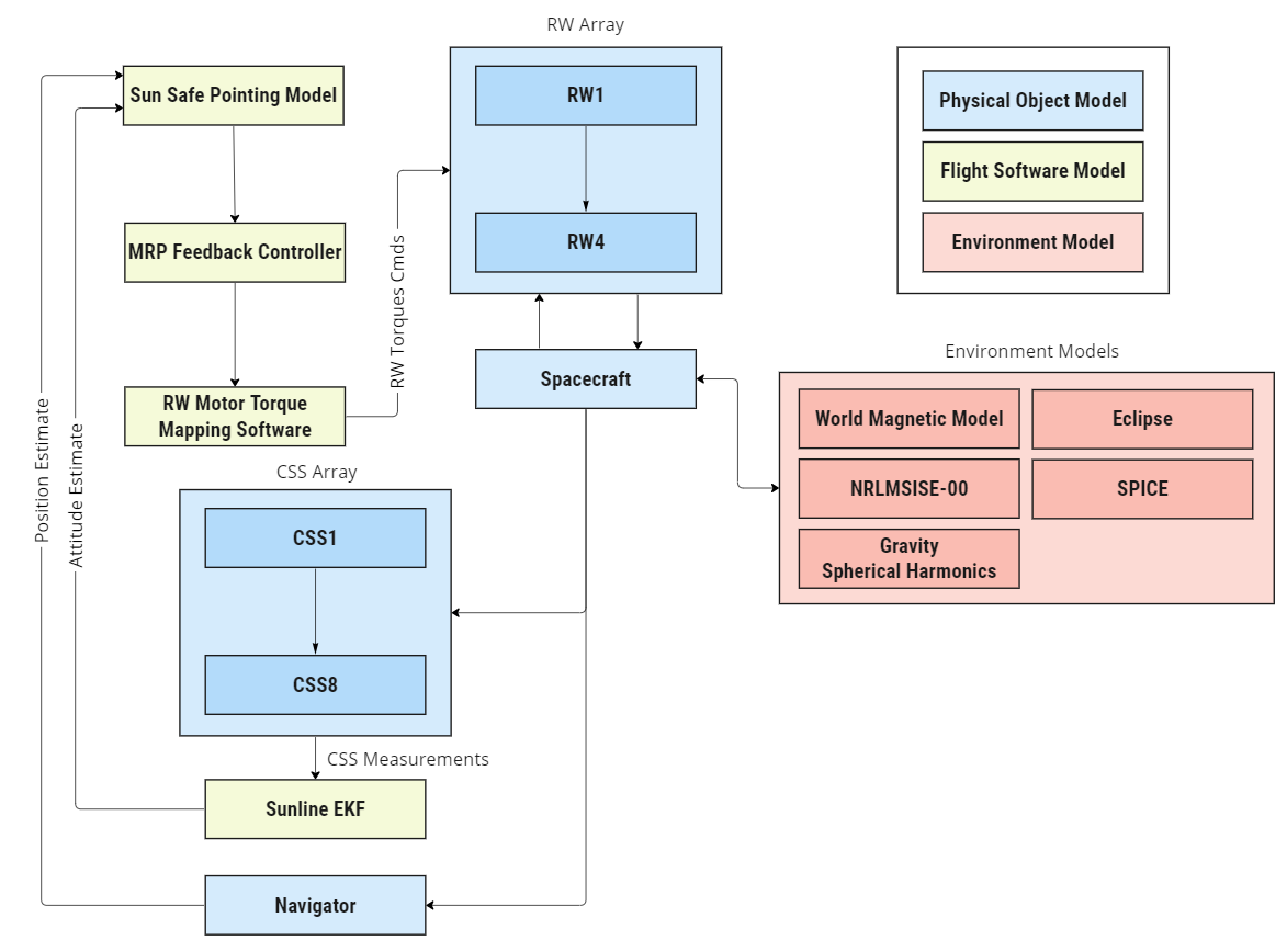
Logic Flow Chart
The diagram below provides a high-level breakdown of the core elements that compose this simulation. This tutorial assumes that the following tutorials have been followed:
- Editor: Configuring a Simulation
- Editor: Configuring a Spacecraft Orbit
- Editor: Configuring a Reaction Wheel Array
In this guide, the focus will be on assembling the spacecraft described in the above image linking the physical components to flight software models manually to achieve the desired pointing mode. Note: The ADCS software chain we shall implement here could also be contained within a custom Computer module configured in either Blueprints or in C#. Examples of this include the Operation Computer and Guidance Computer.
Creating the Spacecraft
Start by configuring a level with a spacecraft spawned in orbit. The spacecraft must have the following components for this example:
- Reaction Wheel Array
- Constellation of Coarse Sun Sensors
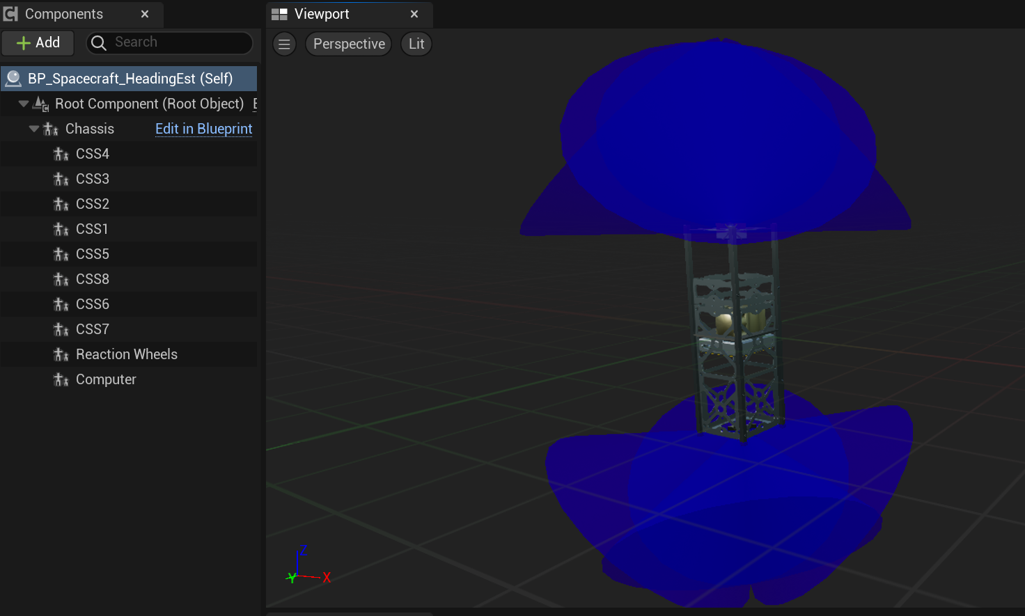
The spacecraft shown below is used in this guide. It is provided within the example spacecraft blueprints (BP_Spacecraft_HeadingEstimation) and has been pre-configured with an array of coarse sun sensors that give sufficient coverage to enable sunline estimates from all attitudes.
Creating the CSS Constellation
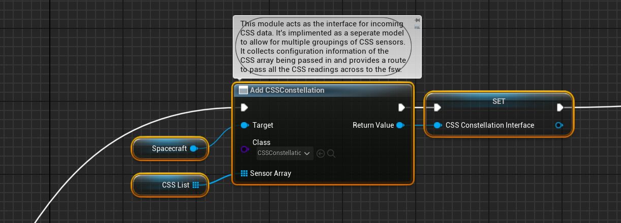
The provided spacecraft does not come with a pre-configured CSS Constellation component. This component acts as the interface between the hardware and software layer, where it collects incoming CSS measurements into an array, which it then passes to flight software models for analysis along with a timestamp of when the measurement was taken.
To add a CSS Constellation component to our spacecraft, use the Add Component By Class method and select CSS Constellation from the dropdown list. You’ll then need to pass an array of Coarse Sun Sensor components as inputs into the model. This is shown below, where CSS List is a local variable from the spacecraft object.
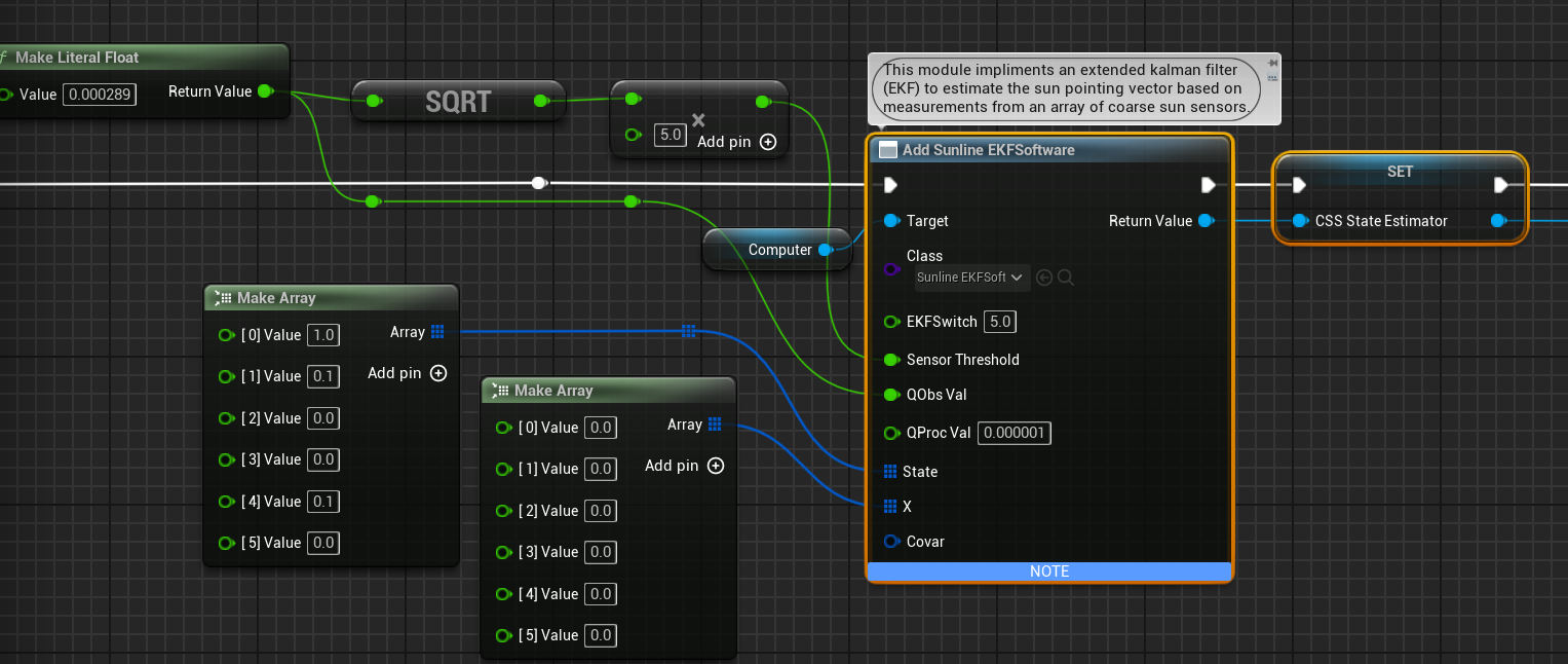
Configure Attitude Estimation Program
The next step is to configure the attitude estimation program used to estimate the spacecraft state based on CSS measurements. Here we use the Sunline EKF model. See the note for more details but in brief, the Sunline EKF uses an Extended Kalman Filter to provide an estimate of the sun-pointing vector based on incoming CSS measurements above a threshold.
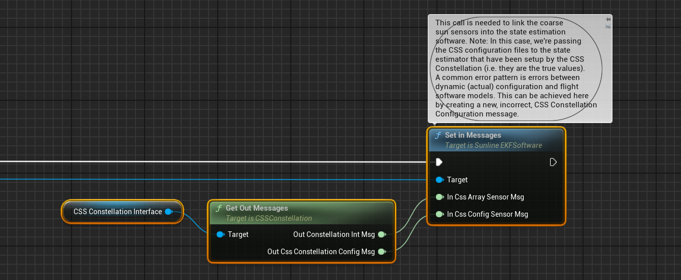
To connect the CSS Constellation to the Sunline EKF module, we need to set the input messages of the SunlineEKF module as below. Here we’ve provided both the configuration of the CSS constellation as well as a link to the measurement from each CSS. An important note to make here is that, by default, the CSS Constellation module provides the true dynamic configuration of the CSS array. A common error in to model is to consider the impact of state estimation when there is imprecise knowledge between the dynamic configuration of a system and the flight software’s knowledge of that configuration. In this case, we would create a custom message for the CSS Constellation’s configuration to model this effect.
Configuring the Sun Pointing Software
The final step is to connect our estimated state to our standard ADCS software chain. In this case, we’re using the Sun Safe Pointing module and passing in our estimated sunline pointing vector into the input sun direction message.
