Editor: Configuring a Spacecraft Orbit
Description
For spacecraft simulations, a typical starting piece of information is to assume that the spacecraft is in orbit around somebody at the start of the simulation. There are several ways to initialize an orbit; including state vectors, orbital elements, geodetic elements or a two-line element. Nominal Editor allows for several orbit initializations to be made. This guide shows how to configure various spacecraft orbits.
State Vectors
For the spacecraft simulation, the orbit state is composed of two values that can define the position and direction of the spacecraft:
- Position: Expressed as ‘\(r\)’, the position defines where the spacecraft is located in inertial space
- Velocity: Expressed as ‘\(v\)’, the velocity defines the directional speed in which the spacecraft is moving, relative to inertial space.
All forms of initialization of orbits will be converted to a state vector of some sort about some celestial body. This is the simplest way to initialize a spacecraft in a simulation. To set the state vector, take any spacecraft (even an empty class) and call the Set Vector Elements function. This will take in a structure and an orbiting body. Setting the Vector Elements will initialize the spacecraft with a position and velocity relative to some planet's body.
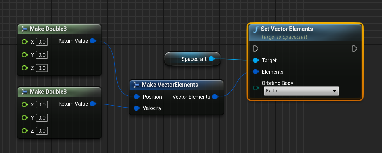
The Vector Elements structure has two Double3 components that can be set to define the position. Note that here, setting a position of 0, 0, 0 will result in the spacecraft being located in the centre of the orbiting body. Additionally, as with all of the initial orbit functions, the position and velocity of the body selected will be added to the values calculated. For example, in the below screenshot, the result of the two different orbits, even though they come from the same state vector, will not be identical. This is because the positions and velocities of the orbiting bodies are not the same.
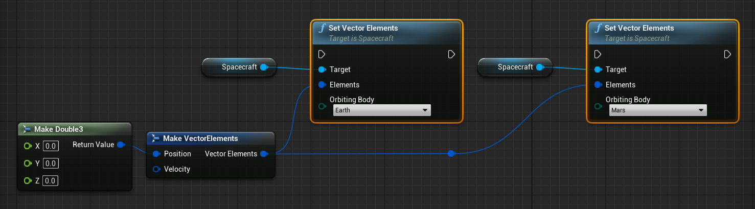
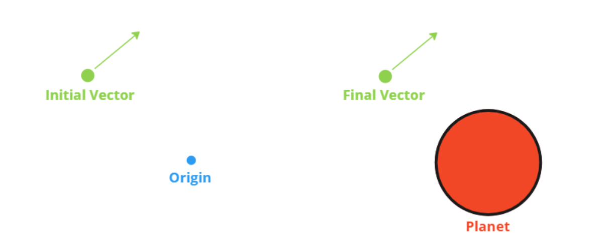
The final vector calculated will be about the planet as the initial vector is about the origin, with both the position and velocity being affected by the planet’s state at the time of initialization.
Classic Elements
A standard set of classical orbital parameters, known as the Keplerian Elements, can define any orbit about a spherical body with six unique parameters. These are:
- Semi-Major Axis: Denoted as ‘\(a\)’, the semi-major axis defines the average distance of the spacecraft to the centre of the orbiting body.
- Eccentricity: Denoted as ‘\(e\)’, the eccentricity defines the shape of the ellipse, with
0being circular and1being hyperbolic. - Inclination: Denoted as ‘\(i\)’, the inclination defines the verticle tilt of the ellipse concerning the reference plane. This is typically between
-180and180degrees. - Longitude of Ascending Node: Also known as Omega Ascension or RAAN, denoted as ‘\(\Omega\)’, this value orients the ascending node of the ellipse, where the orbit passes from south to north through the reference plane, concerning the reference frame’s vernal point. This is typically between
0and360degrees. - Argument of Periapsis: Denoted as ‘\(\omega\)’, this parameter defines the orientation of the ellipse in the orbital plane, as an angle measured from the ascending node to the periapsis point. This is typically between
0and360degrees. - True Anomaly: Denoted as ‘\(f\)’, this parameter defines the position of the spacecraft along the ellipse at the given epoch. This is typically between
0and360degrees.
The spacecraft can be positioned in an initial orbit using these elements by calling the Set Classic Elements function on the spacecraft object.
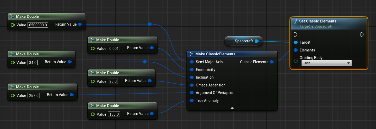
For the four angles, the default values are in degrees for the inputs on the Classic Elements structure. However, there is an option to set the classical elements in radians instead of using the Set Classic Elements (Radians) function. In both cases, the ‘\(a\)’ value is defined in meters and is not equivalent to altitude, but distance from the centre of the body. As a general rule of thumb, when orbiting the Earth, ensure \(a > 6371000\).
Geodetic Elements
The geodetic element initialization allows a user to specify the geodetic coordinates of a spacecraft in orbit with the following elements:
- Latitude: Denoted as ‘\(\varphi\)’, the latitude is the degrees above the celestial equator where the spacecraft is located. This is typically between
-90and90degrees. - Longitude: Denoted as ‘\(\lambda\)’, the longitude is the degree at which the spacecraft is located about the prime meridian of a celestial body. This is typically between
-180and180degrees. - Altitude: Denoted as ‘\(h\)’, the altitude is the distance from the surface (assuming a spherical body) where the spacecraft is located. This must be any value greater than
0.
Although these coordinates define the position of the spacecraft when converted to the vector elements using the planet’s epoch and rotation frame, the velocity of the spacecraft is calculated such that the spacecraft is in orbit with the following rules:
- The spacecraft is in a circular orbit, with \(e=0\).
- The spacecraft is located at latitude \(\varphi\), longitude \(\lambda\) and altitude \(h\) when \(f=0\).
Implicitly, this means the following:
- The semimajor axis \(a\) is set such that \(a = h + R_\mathrm{planet}\), where \(R\) is the radius
- The eccentricity \(e= 0\)
- The inclination \(i\) is set such that \(i=\varphi\)
- The ascension \(\Omega\) is set such that \(\Omega = \lambda - 90\)
- The periapsis argument \(\omega\) is set such that \(\omega = 90\)
- The true anomaly \(f = 0\)
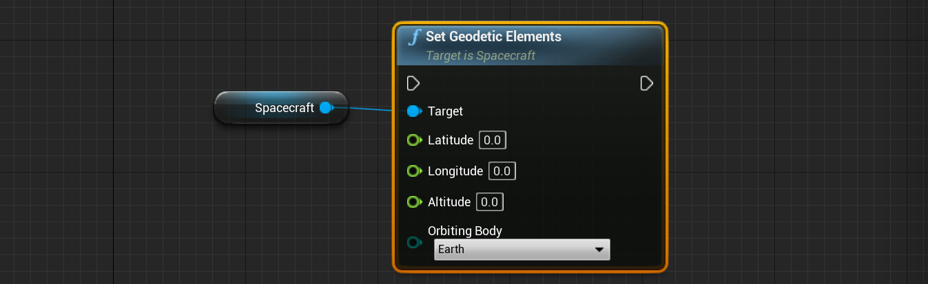
To initialize the spacecraft in a geodetic location in Editor, the Set Geodetic Elements function can be used.
Two-Line Elements
A Two-Line Element (TLE) is a data format that encodes a list of orbital elements for multiple objects at a given epoch. Using a prediction formula, the state vector at any point in the future can be calculated, with some accuracy. An example of TLE could be the following:
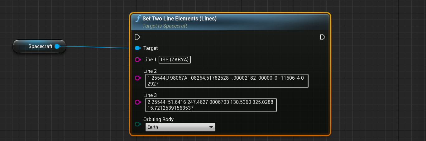
ISS (ZARYA)
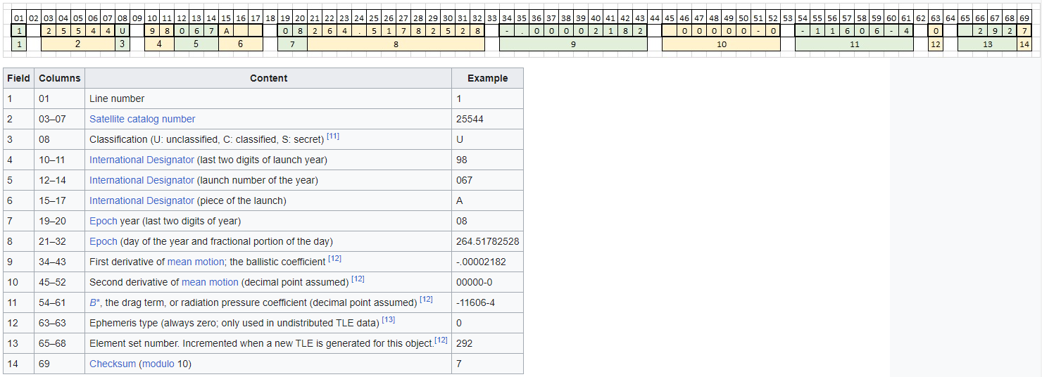
1 25544U 98067A 08264.51782528 -.00002182 00000-0 -11606-4 0 2927
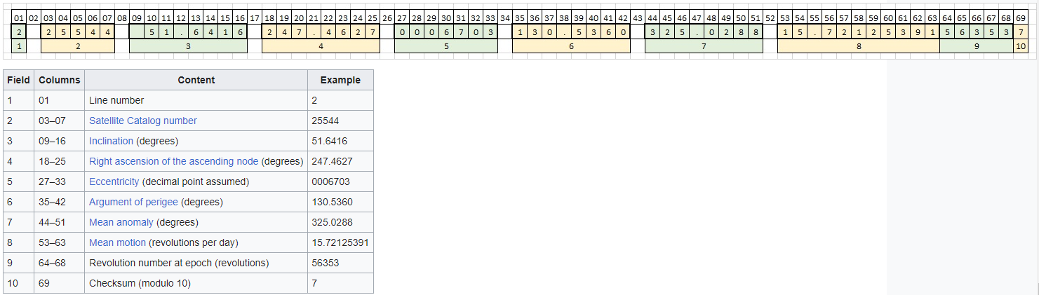
2 25544 51.6416 247.4627 0006703 130.5360 325.0288 15.72125391563537
A TLE file can be composed of multiple objects, but each object must have three lines of data:
- Name: The first line defines the name of the object
- Epoch: The second line includes details about the epoch and average motion of the object
- Orbit: The third line includes details about the current orbit
The two data lines (2 and 3, denoted with the indexes 1 and 2) are structured with an encoding of characters in such a way:
Nominal Editor allows reading of the standard TLE format along with a particular index of the spacecraft. This can be done using the Set Two Line Elements (File) function. Setting a TLE file takes in a standard TLE file that can be read.
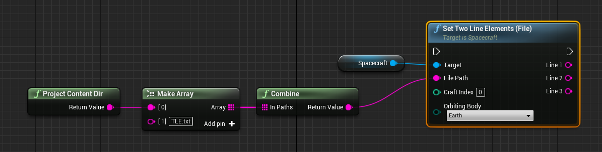
For a file with multiple object parameters, the craft index value specifies which spacecraft, in particular, is being referenced by the reader and which orbit to be initialized in. The function also returns the three data lines for that object as strings, for confirmation checking. The file path must be correct and be relative to the current directory that the application is being run from. Alternatively, rather than reading from a file, the three individual TLE data lines can be manually entered into the method using the Set Two Line Elements (Lines) function.
Sun-Synchronous Orbit
A Sun-Synchronous Orbit (SSO) is a specific type of orbit that is commonly used for Earth observation satellites. In a Sun-Synchronous Orbit, a satellite's orbital plane maintains a nearly constant orientation concerning the Sun, meaning that it passes over any point on the Earth's surface at the same local solar time. The key characteristic of a Sun-Synchronous Orbit is that the satellite's orbital plane precesses around the Earth (or planet) in such a way that it compensates for the orbital motion of the body around the Sun. This results in the satellite passing over any given location on the body’s surface at approximately the same solar time during each orbit.
The advantages of Sun-Synchronous Orbits include:
- Consistent Lighting Conditions: Because the satellite passes over a specific location on Earth at the same local solar time during each orbit, the lighting conditions on the Earth's surface are relatively consistent. This is particularly important for Earth observation satellites, as it allows for consistent illumination and shadowing of the observed area.
- Optimal Imaging Conditions: Sun-synchronous orbits are often chosen for Earth observation missions because they provide optimal lighting conditions for imaging and remote sensing. This consistency aids in comparing images taken at different times and helps in monitoring changes on the Earth's surface.
- Thermal Control: The relatively constant lighting conditions also simplify thermal control for satellites, as they can be designed with a consistent thermal environment.
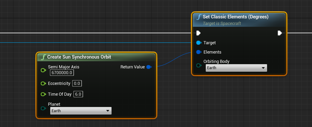
In Nominal Editor, the function is Create Sun Synchronous Orbit, which will produce a classical element set that can be passed into the Set Classic Element function. This orbit includes four parameters:
- Semi-Major Axis: The distance from the orbiting body to the spacecraft’s orbit in meters.
- Eccentricity: The eccentricity of the orbit between 0 and 1. Certain eccentricity values will NOT be able to produce a valid SSO orbit.
- Time of Day: The time in hours between 0 and 24 to cross the equator at each point during the solar day around the planet.
- Planet: The orbiting planet to put the spacecraft around.