Editor: LVLH Pointing Chain
Description
This guide showcases how to create an LVLH pointing chain on a spacecraft. This chain is designed to direct a camera or antenna’s normal direction towards a planet’s ephemeris; most likely Earth. Although, the software is customizable such that any planet or celestial body can be pointed at. A use case would be an imaging spacecraft that would image the Earth as it orbited.
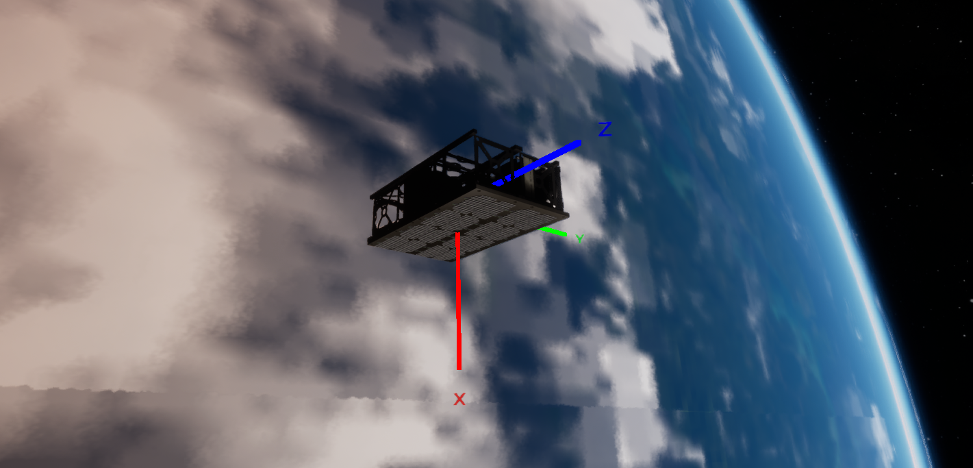
This example scenario can be found at the Payloads/Demo_CameraPayloads level. It uses an external force torque (although this example explains how the reaction wheels can be configured) to orient the spacecraft's attitude to image the Earth’s surface.
Creating the Spacecraft
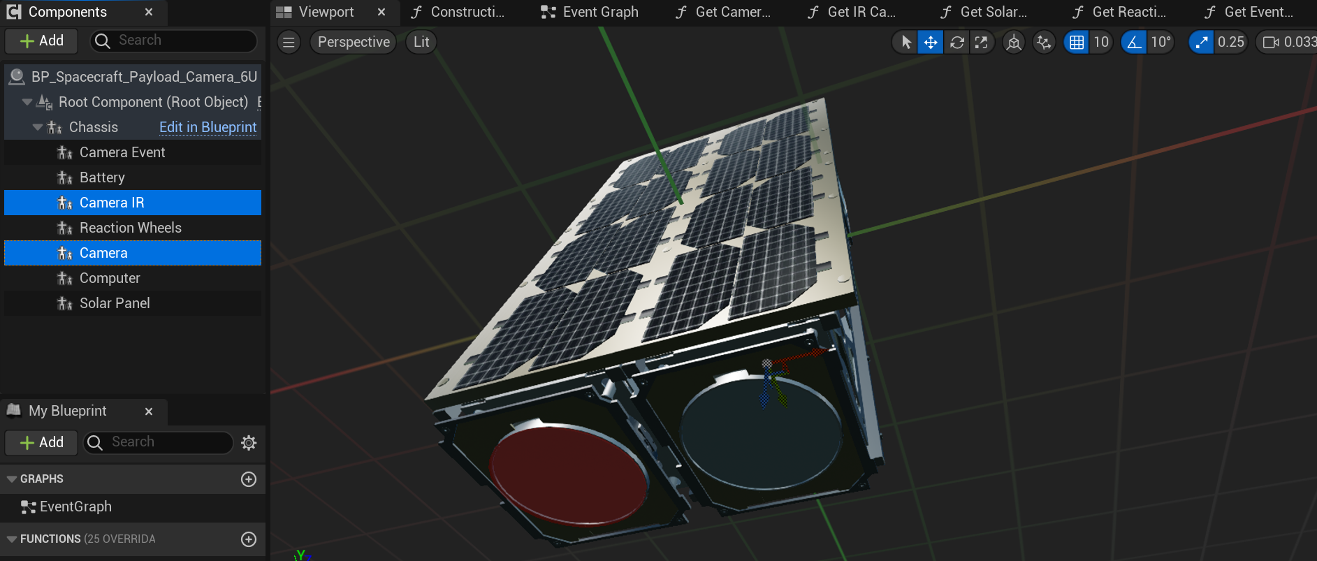
Start by configuring a level with a spacecraft spawned in orbit. The spacecraft must have the following components for this chain to work:
- Reaction Wheels
- Computer
- Camera
The spacecraft can have any other number of components and can have multiple cameras. For this software chain, the first camera (or the top one in the hierarchy of the spacecraft editor) will be the primary camera that will be used as the direction vector. The spacecraft shown is used for this guide.
Adding the Navigator
Next, after spawning the spacecraft in the level blueprint, flight software can be added to the spacecraft. This is usually done in a blueprint function but can be done directly on the Event Graph. The first step is to add the Navigator component. This is required for all flight software chains, and the LVLH-pointing chain is no exception. The Navigator produces the estimated position and rotation of the spacecraft, with some noise values applied. It is a source of truth and does not simulate the data from a sensor. This component needs to be added to the Computer on the spacecraft, which can be done by first fetching the computer and constructing the Navigator.
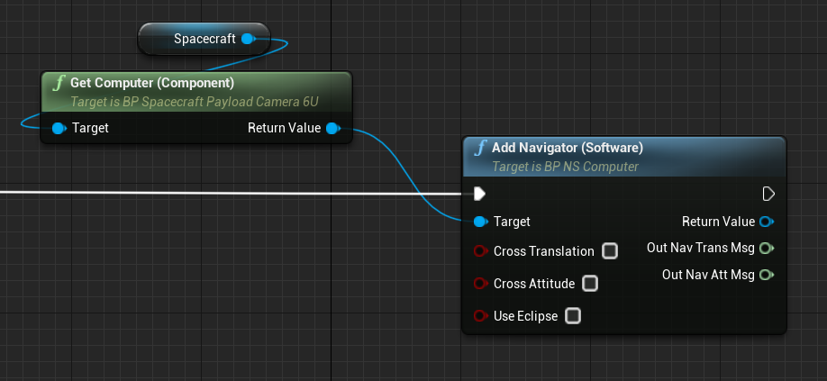
The Navigator takes three input flags, which define how the errors are added to the module:
- Cross Translation: A flag that defines a position error depending on its velocity
- Cross Attitude: A flag that defines an attitude error depending on its attitude rate
- Use Eclipse: A flag that defines whether the sun pointing vector on the navigation attitude message depends on whether the spacecraft is in an eclipse. This flag is only useful for the sun-safe pointing chain.
Adding the Ephemeris Conversion Software
The next software will convert a planet’s ephemeris message, which defines the coordinates in the inertial frame, of the targeted celestial body. This is the Ephemeris Conversion Software and allows for any celestial body, including the Earth, to be targeted with the flight software. The Universe can be used to fetch planet data and the conversion software will create a converted message. In this example, the input message is hidden with the option of selecting the targeted body.
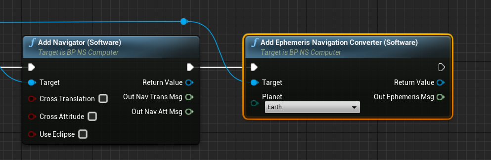
If adding the component manually using the construct from class option, the input planet vector will be exposed and this can be retrieved from the Universe’s Get Universe Planet method.
Adding the LVLH Pointing Software
The next software to add is the LVLH Pointing Software, which will define the guidance error between the current spacecraft state (with the errors defined by the navigator) and the ephemeris vector. This module takes in two input messages, coming from the translation guidance message, containing the spacecraft’s current location and the planet’s location. The software module outputs a reference message, which is the body frame vector that represents the targeted reference frame that the spacecraft needs to orient towards.

Adding the Attitude Reference Correction Software
Unlike the other software chains, the LVLH chain is unique in that it uses a reference change in orientation to calculate the frame at which the spacecraft should orient. The Attitude Reference Correction Software takes the previous attitude reference message, which was created by the LVLH pointing software, and adds rotation to the frame. Since these rotations are represented as an MRP vector, in the corrected body frame, these can be tricky to manipulate. The Sigma BcB parameter defines the additional sigma that will be compounded to the reference frame for the targeted direction of the vector.
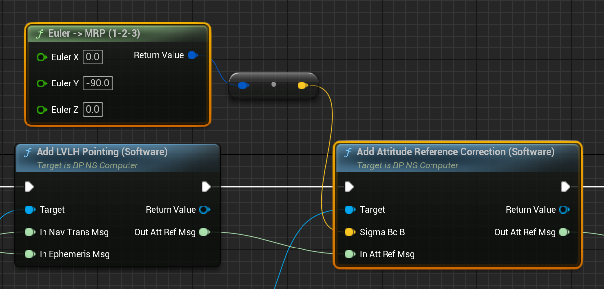
A useful method is the Euler -> MRP method, which calculates an MRP vector based on an array of Euler angles in degrees. Finding the exact angle can be tricky without knowledge of MRP systems.
Adding the Attitude Tracking Error Software
The next module to add to the chain is the Attitude Tracking Error Software, which takes in both the current reference frame that is targeted (in the body frame) and the current spacecraft attitude message (which can be found from the navigator on the first software module added) and determines the guidance frame that would rotate the spacecraft towards the reference. It computes the frame difference and produces the output that can be fed into a PID controller module. Without the tracking error, the reference frame is not enough to determine the correct torques for a spacecraft to reach its desired attitude.
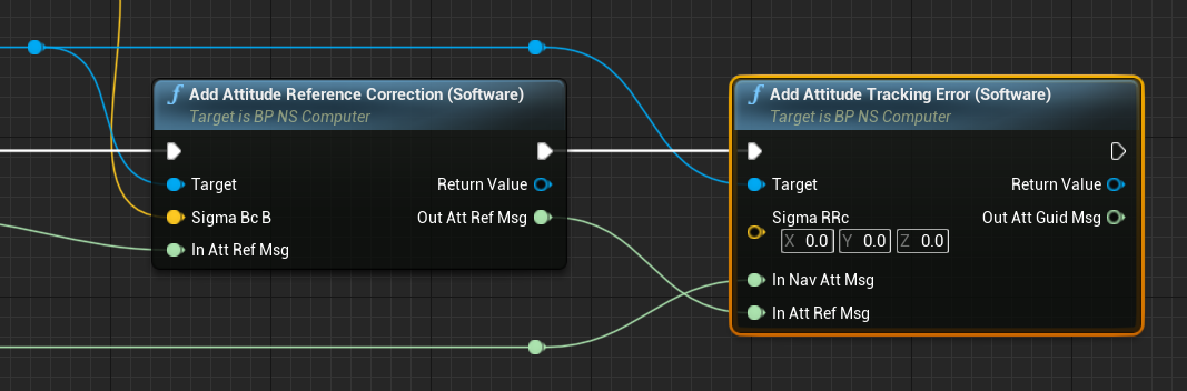
An optional parameter is the Sigma RRc, which defines the corrected reference frame parameter. By manipulating these values, it can define a fixed frame rotation to the corrected reference frame \(R_c\) from the reference frame \(R\).
Adding the MRP Feedback Software
A standard software module that is used for all pointing chains is the MRP Feedback Software. This software module takes in a desired guidance direction and compares the direction with the current orientation. It then uses a PID controller to create a torque message that will define how much torque is given to the effectors (such as a reaction wheel or external force module) to start orienting the spacecraft in the desired vector. The guidance message is a requirement as the input for the module, however, the reaction wheel messages (speed, availability and config) are optional and can be used when a reaction wheel exists. These messages provide information to the controller on the configuration and speed of each reaction wheel and can optimize the controller for specific wheels.
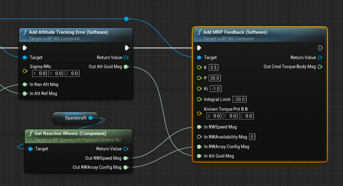
The MRP controller is configurable and the PID constants can be adjusted. These parameters are dependent on the state of the system and the friction models on the reaction wheels. The default constants are suggestive and work in a majority of use cases.
- K: The proportionality-gain constant (P) to the MRP errors.
- P: The rate-error constant (D) for the feedback gain.
- Ki: The integration feedback error constant (I) on rate error.
- Integral Limit: The integration limiting torque to avoid wind-up issues.
- Known Torque Point B_B: The defined additional external torque, defined in body frame coordinates, that is applied to the controller.
Adding the Reaction Wheel Motor Torque Software
The MRP controller will return an expected torque for some effector to apply on the spacecraft in the body frame. If a reaction wheel module is used, then this torque needs to be converted to a reaction wheel command, that can be sent to the reaction wheel array on the spacecraft. This is the Reaction Wheel Motor Torque Software and it takes in the state of the reaction wheels (as a configuration message) and the required torque command and produces an array motor torque message, containing a list of torques that are to be applied to a reaction wheel. By default, if no availability message is defined, the module will assume all reaction wheels that are configured are available and operable in the system.
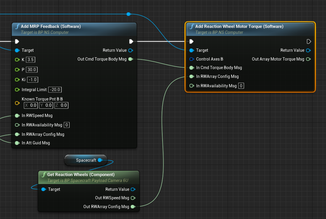
The reaction wheel motor torque software has one additional parameter, defined as the control axes. This parameter defaults to the identity matrix but can be configured to define a non-symmetrical axis of control, in the case that a reaction wheel or software produces the torques in a rotation that is not equivalent to the reaction wheel direction vectors.
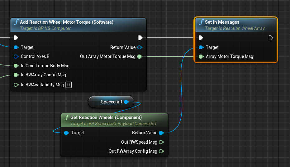
Connecting the Reaction Wheel Message
The reaction wheel motor torque software produces an array message that the reaction wheel uses to control the torques of each wheel. The final task of the flight software chain is to connect the message to the reaction wheel. This can be done using the Set In Messages method, which is the standard syntax for updating the input messages of a component.
These are all the required software modules for the LVLH-pointing chain to be implemented on a spacecraft. Additional software modules can be added for specific use cases, such as a power voltage conversion.