Spacecraft: Configuring the Universe
Navigating the Editor
The scenario blueprint is the most common place for configuring a simulation. Blueprints allow for visual scripting code to be placed in the editor and configured for a simulation. Any Unreal asset, both in blueprints or in C++, can be accessed within the editor and certain functions are exposed to be used here. The window will look like the following once opened:
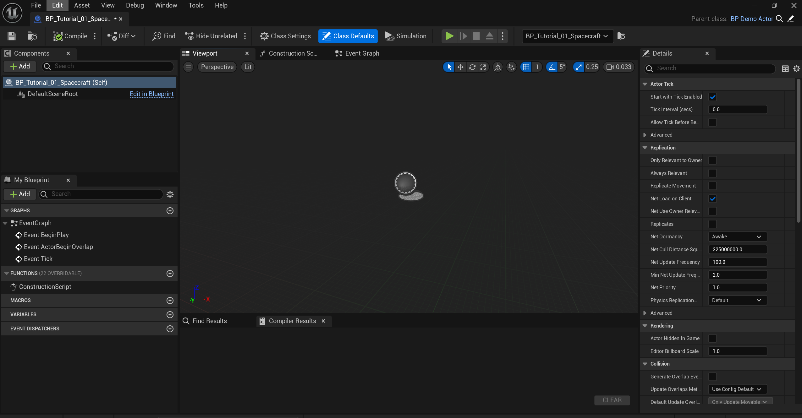
Since this is a scenario Blueprint, no components are required to be created. Instead, click on the Event Graph for the visual scripting nodes. The Event Graph will have a large area for adding in Blueprint visual nodes for visual scripting.
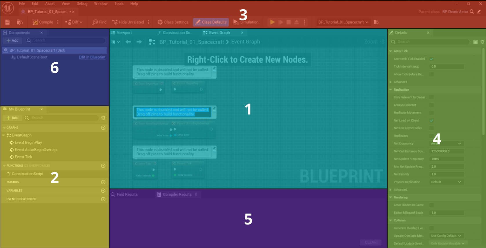
1. This is the blueprint graph. This will display all of the blueprint and visual scripting nodes that have been added to the level. The graph will display the function that is being opened or, in the case of the general coding event, the event graph. All nodes will be written in this panel.
2. This is the outliner. This panel will show off all of the functions, variables and events that have been exposed to this blueprint. When a new blueprint or level is constructed, only the Event Graph is displayed here. All levels must have this graph. Additional functions and variables can be created, which will show as an unordered list in this panel.
3. This is the toolbar. The toolbar includes the buttons required to compile the code and change some of the properties of the blueprint. The main buttons here are the compile, save and play buttons. These are standard to the Unreal Engine and Nominal makes no additional changes to this functionality.
4. This is the details panel. When a specific blueprint object, such as a function or variable, is selected, the panel will provide options for customization of the type and the exposed parameters. Configuring code will be found in this panel once the blueprint types are selected. By default, the panel will show information about the level blueprint, which in almost every case, must remain unchanged.
5. This is the compiler. The panel will show any blueprint compile errors or bugs in the code. If there are issues with developing the blueprint code, they will appear here. By default, the panels will be hidden unless they are selected by clicking on the options.
6. This is the component view. The panel is useful for creating custom assets but is not used for creating simulations. This view will not be useful for scenario creation.
Event Graph
The Event Graph is a node-based system that allows users to define the behaviour of objects and characters by creating a series of events and actions. In the Event Graph, you can create nodes that represent events such as player input, collision detection, or timer events. These events can trigger various actions or functions, such as spawning a spacecraft or running a simulation.
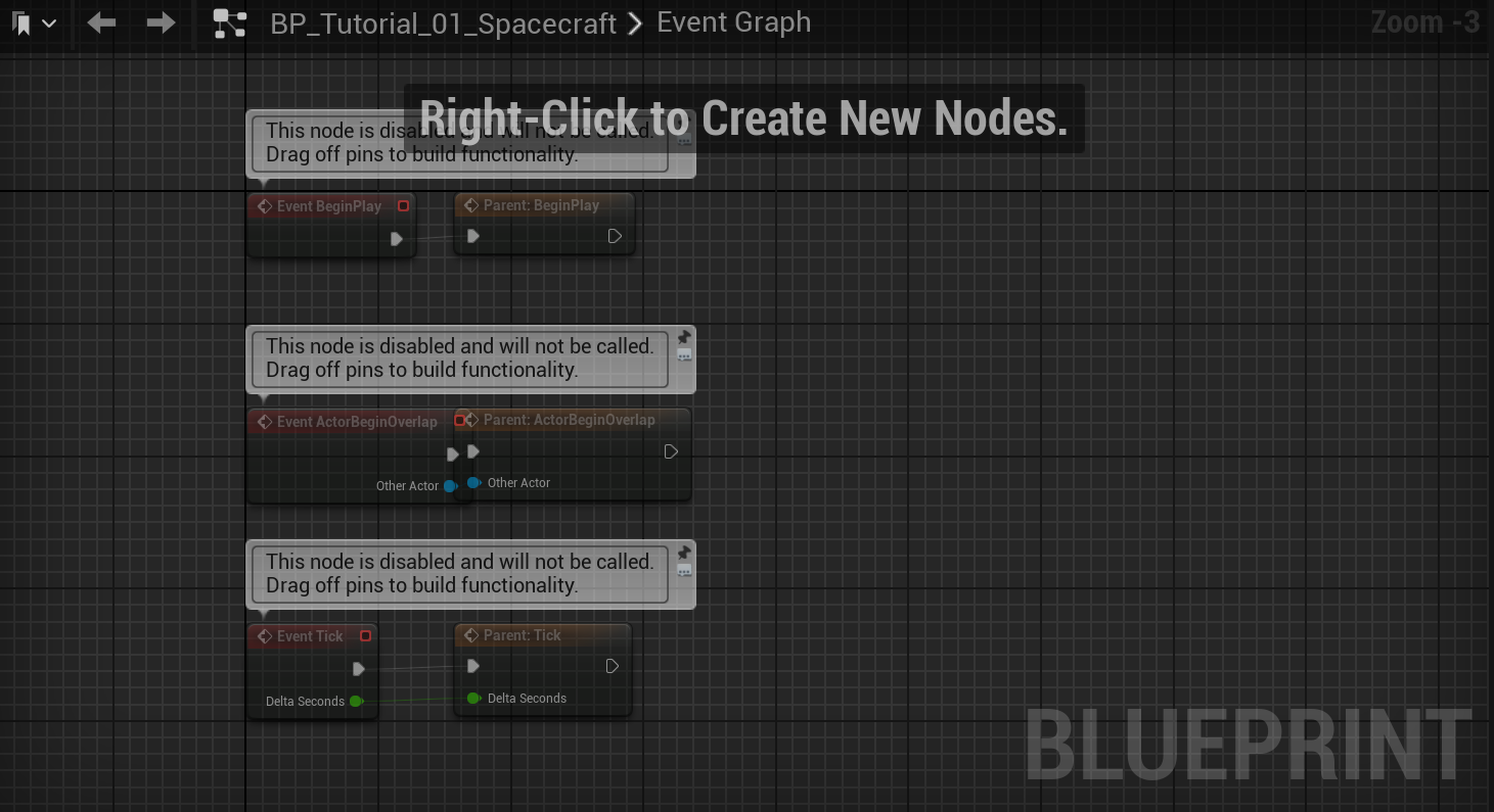
By default, three events exist in the event graph; disabled.
- Begin Play: This event is executed when the level starts running and will run once. This is typically used to spawn all spacecraft and configure the simulation.
- Actor Begin Overlap: This event is called when the object overlaps another object. This event will not be used and can be deleted.
- Tick: This event is executed every Unreal frame (not simulation tick), which may be up to 60 times a second depending on the hardware capabilities. This event is typically used for running the simulation and updating the user interface.
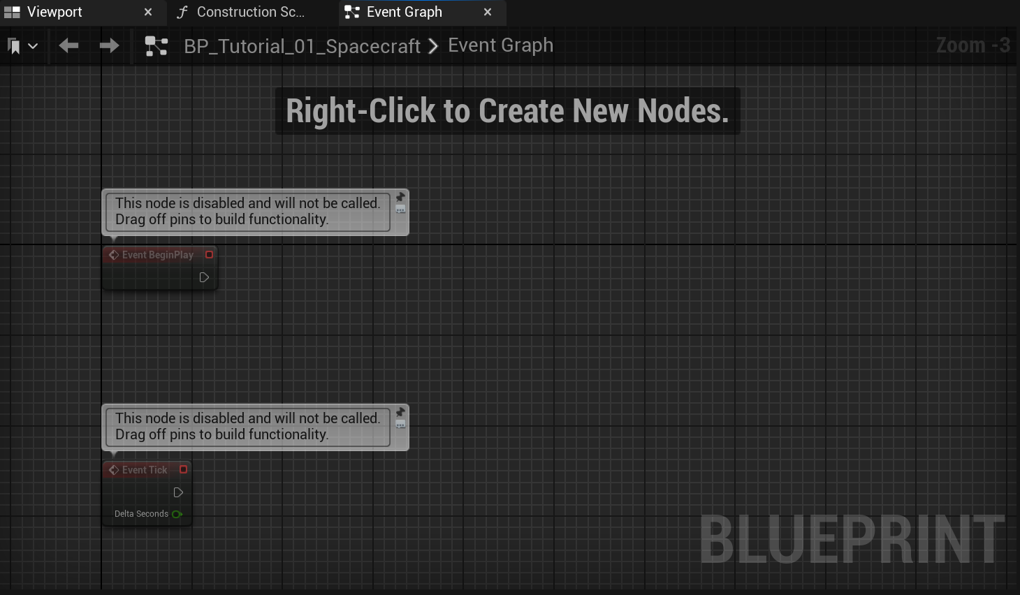
For most simulations, only the Event Begin Play and Event Tick functions are required. Delete the parent calls and the other events by selecting the events and hitting the delete key on the keyboard. At the end of this, the level graph should look ready to go.
Many other events, such as input events, can be added to the event graph. This tutorial will not cover how these events can be configured but are standard Unreal Engine events. Information on the event graph can be found below.
Creating a Function
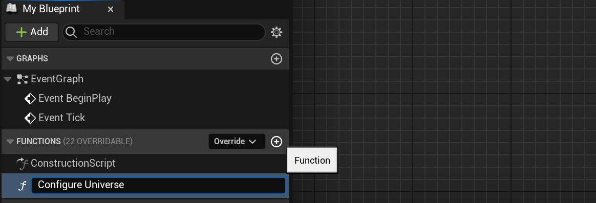
Although all of the blueprint code can be written on the event graph, it is best practice to group blueprint code into function blocks. Each function has a specific purpose, may have some input and output variables and can repeat multiple times if necessary. To construct a new function, navigate to the outliner and click the plus button on the functions tab. The first function will be the Configure Universe function.
In the details panel, information about the inputs and outputs of the function are shown. These can be edited later and do not need to be defined immediately. To open up different functions or the event graph, double click on the items in the blueprint panel.
Setting up the Universe
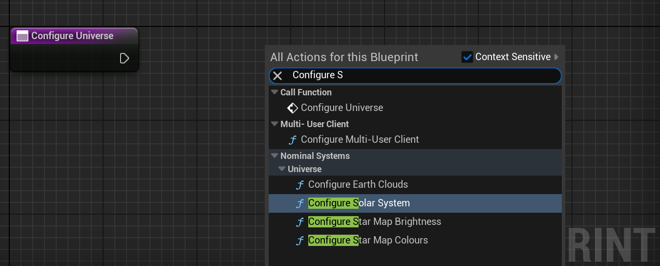
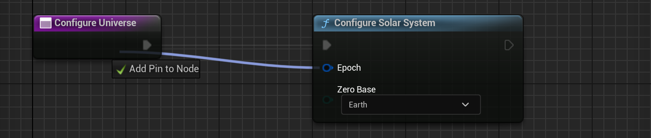
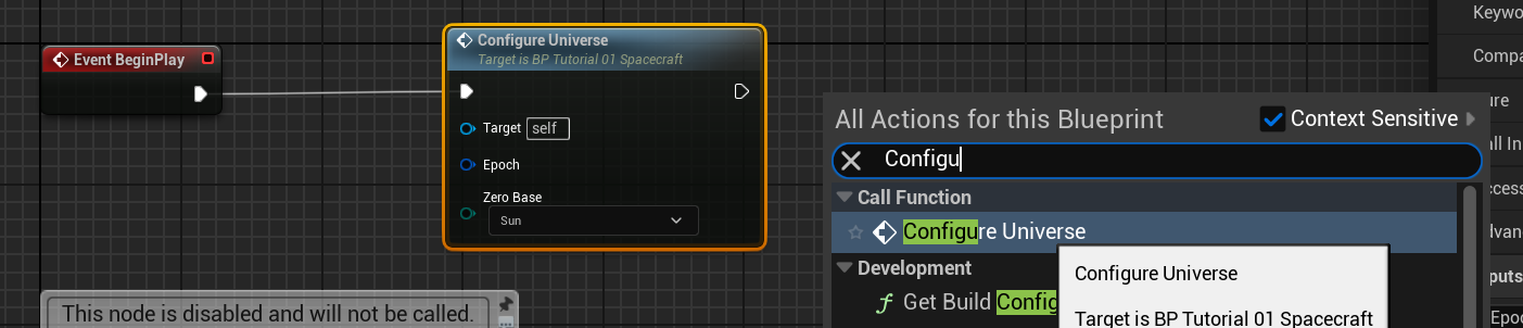
For space domain simulations, the Solar System provides the context of the simulation epoch, celestial bodies and objects that exist within the simulation. This system will be created in every simulation by default and always exist. By default, this step is not required and the Solar System will initialize the starting epoch to be the current date-time and the central body to be the Earth. However, the Solar System can be called in the Blueprint editor and those initial values can be adjusted to some custom ones. Right-click on the event graph and search for the Configure Solar System function. This should be under the Nominal Systems ****tab.
This function provides two inputs:
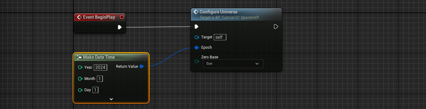
- Epoch: The current timestamp of the simulation in UTC. To adjust the Epoch, a pin must be dragged out and the
Make DateTimenode must be connected to this input. - Zero Base: This defines the central location of the coordinate system. By default, this will be located on Earth. This means that the position
0, 0, 0is situated in the centre of Earth.
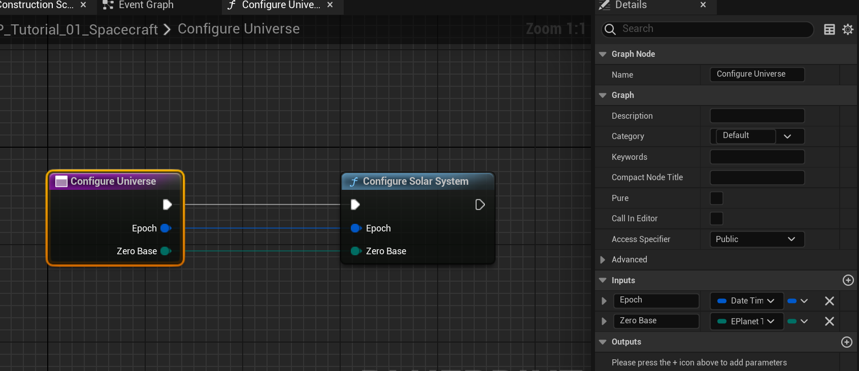
To connect the function execution to the function call, the white execution line must be drawn between the function input (the purple node) and the white triangle on the blue function call. This can be done by left-clicking and dragging from the left to the right.

Exposing Input Parameters
Adding inputs to a blueprint function can be easy. Although inputs can be manually added by selecting the function and adjusting the inputs in the details panel, a quick way to add new inputs is by dragging the input from the node onto the purpose function start.
Multiple inputs can be done in this way, provided that the node touches some blank space without another parameter (to avoid a casting). From here, changes to the name of the inputs or type when required can be done using the details panel.
Note
The same process can be done for outputs. This function requires no outputs, but by selecting the Output Node from the blueprint search and dragging in the variables to output, the values can be exposed to the right of the function call.
Calling the Function
Once a function is created, it is important to add it to the Event Graph. In this case, the configure universe function needs to be added to the Begin Play event. Drag or find the function call from the blueprint search and connect up the nodes from the event call. This will enable the event if it is the first function in the list.
To set the epoch, left-click and drag off the Epoch pin and search for Make Date Time. Set the values of the date-time to something reasonable. For example, setting the level to the year 2024 on the 1st of January.
Note
To change the time of the hours, minutes, seconds and milliseconds, press the drop-down button on the Make Date Time structure to reveal the hidden properties. The date time will be invalid if any of the first three numbers are left as 0. The smaller values can be left as 0 for valid data.
Running the Level
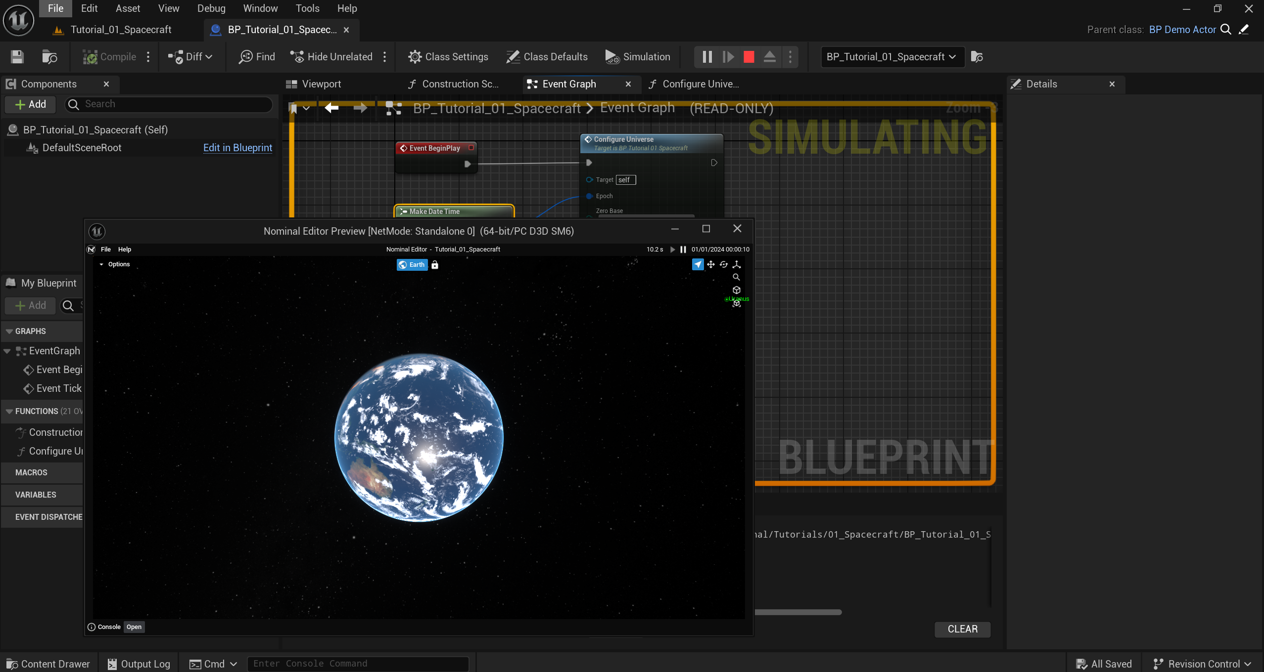
Whenever enough changes have been made, to run the level make sure to compile the blueprint assets. This button is located in the toolbar. Hit the save button as well to make sure the changes are not lost. When the play button is pressed, a new window (or the viewport) will start running the level. Without any simulation objects, the level should showcase the Earth in the centre of the world and nothing else.
Note
To stop the level, either close the window or press the stop button in the toolbar. Blueprint coding can continue from there. Code can not be changed or edited while the level is simulated.