Data Downlink: Configuring User Interface
Adding the Map
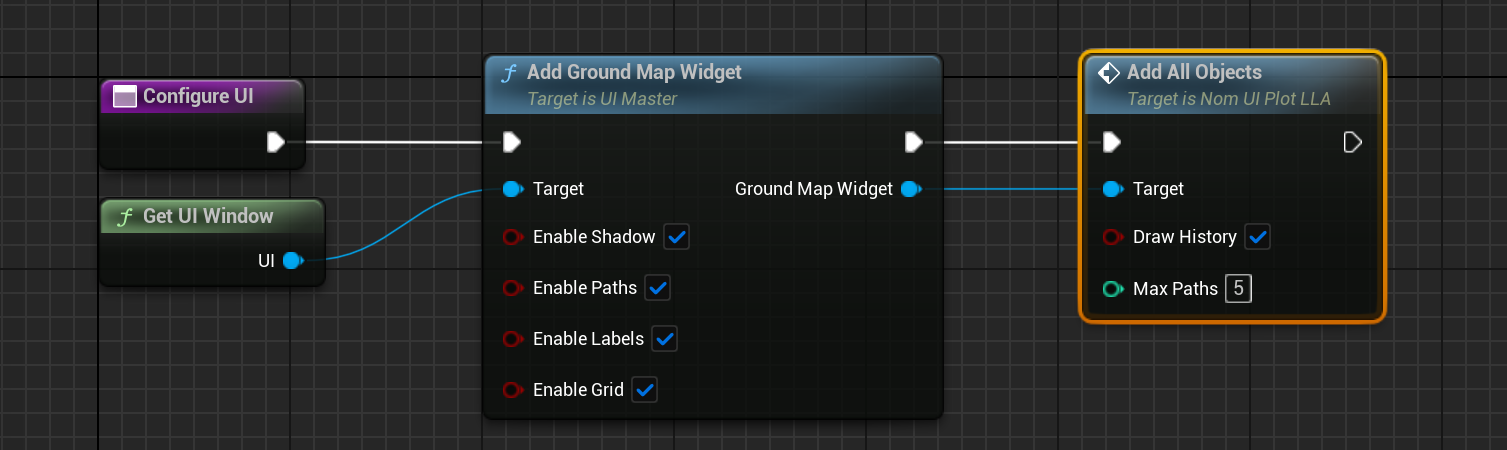
Similar to the previous tutorial, the user interface (UI) can be added by creating a new function called Configure UI and by adding elements to the Get UI Window. The first widget is the Map widget. This can be done by calling Add Ground Map Widget. This includes a number of parameters:
- Enable Shadows: This adds in the sun-projection shadow to the map, showing the parts of the Earth that are lit up by the Sun.
- Enable Paths: A flag whether to draw the path across the Earth that the spacecraft is moving in or not.
- Enable Labels: A flag for whether to show the names of the ground stations and spacecraft on the map widget.
- Enable Grid: This will display latitude and longitude lines on the map if enabled. Otherwise, a flat image of the map will be shown.
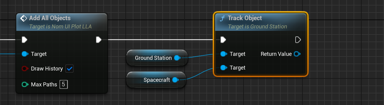
Then, on the widget object itself, the objects have to be added. To register the spacecraft and the ground station, call the Add All Objects function.
Note
Individual spacecraft and ground stations can be added, but this function will find all spacecraft and ground stations that exist in the simulation and add them to the plot.
Tracking a Spacecraft
Ground stations can track spacecraft. This means that they can determine the relative azimuth, elevation and slant range from the station. Provided the values fit within the ground station’s configuration, an access flag will be enabled. Using this tracking, the TT&C system will be overridden to ensure that only when the ground station to spacecraft has access will the transmitter be able to communicate with the receiver. The Track Object function on the ground station will enable tracking of the spacecraft and will produce an access message.
Messages are the backbone of the Nominal simulation. They can connect data flows between components and store a structure of data embedded within the message. This system will be covered in more detail in later tutorials.
Note
Messages can either be an output message or an input message. Output messages are created by the component and managed by that component. A message should have a single output point. Input messages are used to connect data to other components to be read, but should not be written by those components. Messages have a one-to-many design, as a single output message can be connected to multiple other component input messages.
Adding a Log
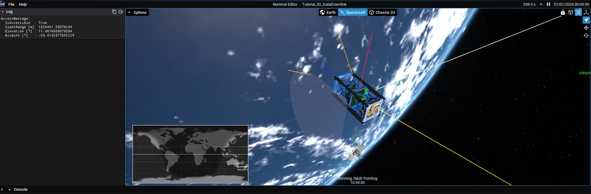
A log widget can display some text on the screen over time. The text can either be written and updated by the user or it can automatically be updated with a message. If a message is parsed into the message parameter, the log will keep track of the message and each frame will print out the converted text of the message, outputting the state of all of the values within the structure. In the case of the access message, this will include the access flag, elevation angle, azimuth angle and slant range.
To add a log widget, call the Add Log Widget to the master UI node. The layout can also be specified, along with a title and colour. This will return the reference to the created widget. From here, the Set Message function can be called and the message that was returned from the ground station tracking can be passed into the function.
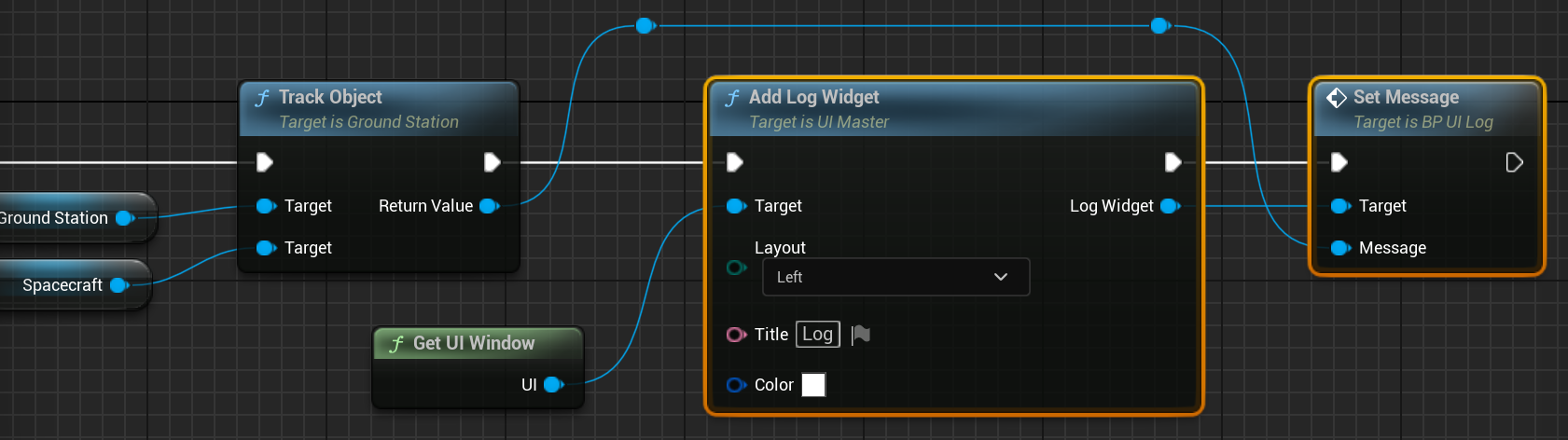
The log can also be given a key, which acts as the title as well as a key for updating the text within the message and a colour for the text. If the message is left blank, the log must be written manually by calling the Set Text function on the log widget.
Visualizing the User Interface
Once the two widgets have been added to the simulation, running the simulation will show the widgets working and changing over time. The text within the log should be constantly updated and the spacecraft should be in access with the ground station at around 150 simulated seconds.