Software: Velocity Pointing
Description
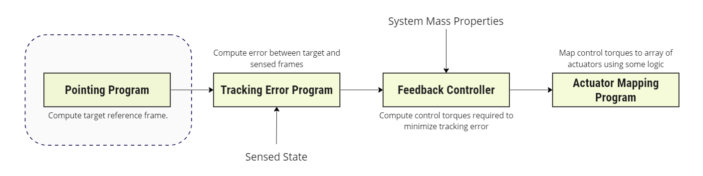
This module is designed to work as the pointing program in an ADCS software chain as shown in the figure below.
This module constructs an output reference frame \(\mathcal{R}\) that aligns with the Velocity reference frame \(\mathcal{V}: [\hat{i}_n, \hat{i}_v, \hat{i}_h ]\) where:
\(\hat{i}_v\): is tangent to the orbit and parallel to the velocity
\(\hat{i}_h\): is normal to the orbital plane in the direction of the angular momentum
\(\hat{i}_n\): completes the right-handed triad.
The Local Vertical Local Horizontal (LVLH) frame \(\mathcal{L}\) and velocity frame \(\mathcal{V}\). These two frames differ by a 3-axis rotation with the angle \(-\beta\).
Example Use Cases
- Compute the velocity reference frame for pointing applications: Constructs a reference frame commonly applied for thrusting operations e.g. thruster alignment with velocity vector for Hohmann transfer.
Module Implementation
Reference Frame Definition
Assuming a frame about the spacecraft, \(\mathbf{R}_s\) is the position vector of the spacecraft in the inertial frame \(\mathcal{N}: [\hat{n}_1, \hat{n}_2, \hat{n}_3 ]\) and \(\mathbf{R}_p\) is the position vector of the celestial body in the inertial frame. The relative position and velocity of the spacecraft in the planet-centered inertial frame are then:
The velocity frame orientation is then defined as:
The direction cosine matrix that maps \(\mathcal{R}\) to \(\mathcal{N}\) is then \([RN] = [\hat{i}_n, \hat{i}_v, \hat{i}_h]\).
Reference Frame Angular Velocity Vector
In classical elements, the DCM mapping \(\mathcal{V} \to \mathcal{L}\) may be written as follows [1]:
The following identities may then be written as:
The derivatives of \(\beta\) may then be written as:
The true anomaly rate and acceleration are then:
The velocity frame angular vectors may then be written in the inertial frame as:
References
[1] Hanspeter Schaub and John L. Junkins. Analytical Mechanics of Space Systems. AIAA Education Series, Reston, VA, 3rd edition, 2014.