Editor: Gimballed Components
Description
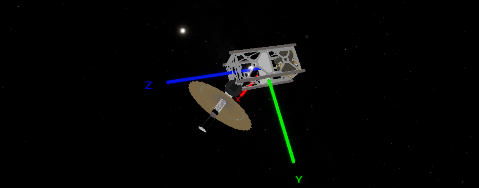
A gimbal is a component that can rotate around a particular 1-dimensional axis. Components can be attached to the gimbal and have their rotation relative to the root object’s frame updated during the simulation runtime. Unlike the hinged rigid body which also performs rotations, gimbals assume that the connection is fixed and structurally perfect, meaning that the gimbals rotation is forced rather than simulated using the physics system. A gimbal is still able to produce torque when rotating during the simulation, which can be calculated based on the inertia and mass of the components attached. The mathematics behind this component can be found in the technical manual section of the documentation. This page will show how to use Nominal Editor to configure a gimbal component. As a reference, the demo level Dynamics/Demo_GimballedAntenna will be used here.
Adding a Gimbal
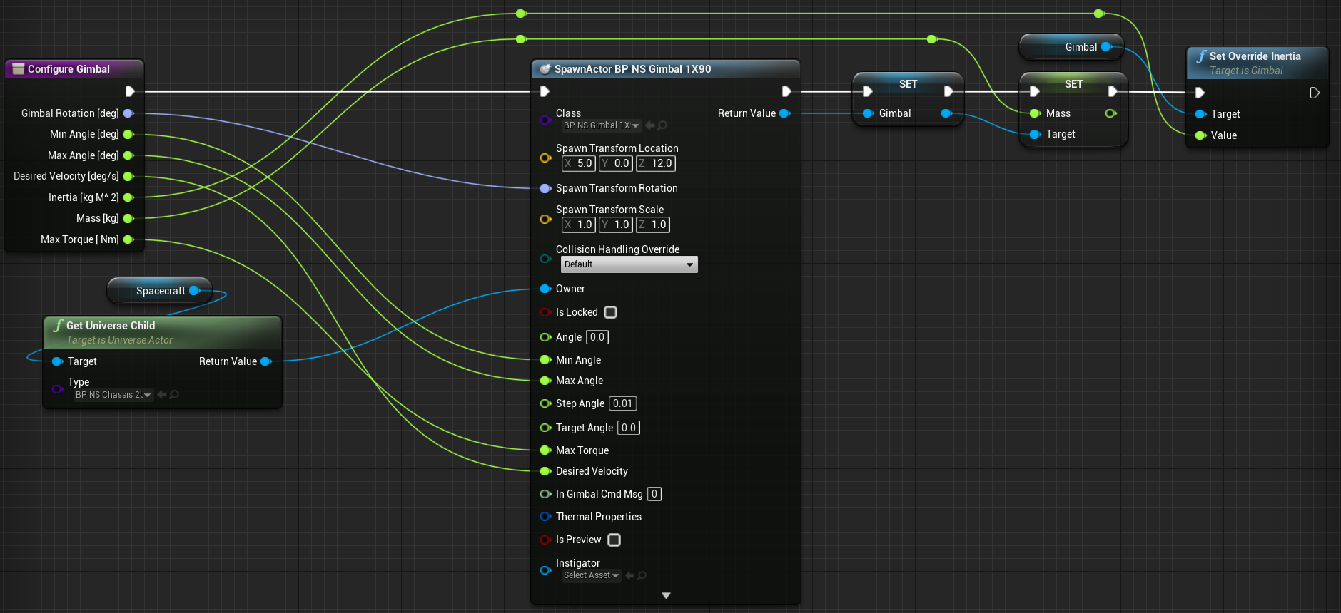
A gimbal is a standard Physical Object actor component. It has a position and rotation and can be added to a chassis using the Spawn Actor from Class method in the blueprint editor. The default assets provide a couple of gimbal options that can be used within the levels. The one used here is the BP_NS_Gimbal_1X90, which is a single-axis 90-degree gimbal.
Note
Gimbals have a fixed range of rotation. Typically, they may have 90, 180 or 360 degrees of motion, but there are no restrictions that the software allows for the range. For a 90-degree gimbal, the target angle starts at 0 degrees and cannot exceed 90 degrees or become negative. This is configurable in the gimbal settings.
Several parameters can be set on the gimbal:
- Is Locked: This will lock the gimbal and prevent any rotation from occurring, regardless if the target angle has been changed.
- Angle: The initial angle the gimbal is rotated on its axis. Typically, this should be left at 0.0 degrees.
- Min Angle: The minimum angle in degrees that the gimbal can reach. This should typically be left at 0.0 degrees.
- Max Angle: The maximum angle in degrees that the gimbal can reach. For this example, it is set to be 90.0 degrees by default.
- Step Angle: This defines the minimum step size the gimbal can move in each step. A 0.0-degree step will simulate a smooth gimbal, while non-zero steps will have rigid and defined movement.
- Target Angle: This defines the angle the gimbal should be moving towards. For most cases, this should be left as default when initializing.
- Max Torque: The maximum torque in Nm that the gimbal can move at. If the torque required exceeds this value, then the gimbal will restrict its rotation speed.
- Desired Velocity: This is the velocity in deg/s that the gimbal should be attempting to move at when the angle is not equal to the target angle.
Additionally, the initial transform, both position and rotation, of the gimbal can be changed. This will define where the origin of the gimbal is located relative to the chassis of the root object. The gimbal will rotate clockwise about the Z (blue) axis of the gimbal’s origin. The gimbal origin does not need to align with the origin of the root object.
Once configured, additional parameters such as the mass of the gimbal component and the inertia of the gimbal can be updated. By default, the gimbal calculates the inertia of the components attached to the gimbal using the formula:
where the inertia \(I\) is calculated from the total mass of the gimbal stack \(M\) and the maximum distance a component is from the origin of the gimbal \(r\). However, this is an approximation made with the cylindrical rotation axis theorem. By overriding the rotational inertia about the rotation axis, a more accurate torque measurement can be made, which can be done by calling Set Override Inertia.
Adding Sub-Components
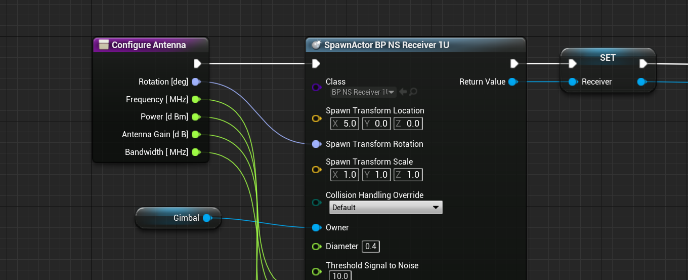
Components that should be rotated with the gimbal can be attached to the gimbal. This can be done by spawning them and connecting the Owner to the gimbal. The rotations and positions of the components are relative to the gimbal’s origin rotation point. These will provide an offset to the rotation that is done when the gimbal begins rotating. In the demo example, a receiver is attached to the gimbal to move towards the Earth when pointing at a ground station.
Note
The only components that can be added to the gimbal must be components that inherit from the Physical Component. Currently, static meshes and other Unreal objects cannot be added directly. Instead, create a new Physical Component blueprint class and add a static mesh there. Then, an instance of that class can be directly added to the gimbal.
Rotating the Gimbal
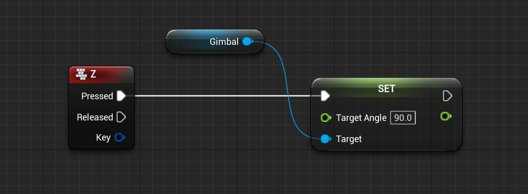
During the simulation, a custom blueprint code can be made to rotate the gimbal to a particular target angle by setting the Target Angle parameter on the gimbal. The gimbal will check its current relative angle from the start point against the target angle and will attempt to change the angle by rotating about the Z-axis of the gimbal origin. This performs a yaw rotation on the components attached. As an example, configuring an event when pressing the Z button to rotate the gimbal to the 90-degree mark might look like this:
Note
The gimbal will attempt to move with the desired velocity as set in the initialization node. If the torque required for this velocity (as per the mass and inertia of the components) is too great, the velocity will be limited by the maximum torque of the system.
Gimbal Messages
Instead of controlling the gimbal using the parameter, a Gimbal Command Message can be used to connect to the gimbal and control the state of the gimbal through the messaging system. This allows for flight software to be written with the messages and connected to multiple gimbals. The demo level uses this method for updating the gimbal state. This is done by setting the In_GimbalCmdMsg parameter to a new instance of the message. This is typically connected on the spawn node but can be done later in the Begin Play event sequence if required.
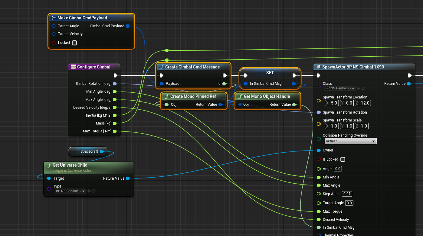
Note
Messages that are owned by the event graph should be pinned using the Create Mono Pinned Ref, otherwise, the reference to the message may be lost with the runtime system, rather than dynamically tracked.
During the simulation, the message can be updated using the Write message function with the new target angle. In this case, once the simulation reaches 300s, the gimbal target angle is set and the gimbal will begin rotation.
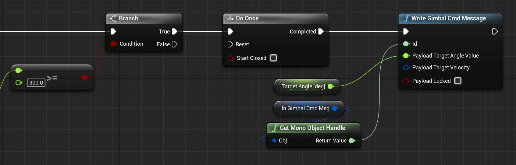
The target velocity value can be left as zero. If zero, it will use the default velocity value set on the gimbal. If non-zero, the rotational velocity will be updated to the value of the input message. This is the same system as the locked parameter. By combining multiple gimbals on top of each other, this system could be used to make a stable inverse-kinematics state machine.
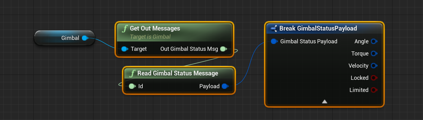
Additional gimbal state messages can be read from the gimbal by using the Get Out Messages function on the gimbal, returning the current angle (in degrees), the torque (in Nm), the velocity (in deg/s) and whether the gimbal is locked or limited. A limited flag will define whether the gimbal has reached its minimum or maximum angle and can only move in one direction.
Stacking Gimbals
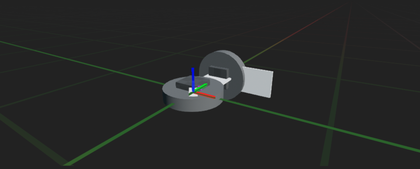
Since the physics of the gimbals has been simplified to improve performance, gimbals can be stacked on top of each other to provide multiple degrees of freedom (DOF) rotations. For example, a 2-DOF gimbal might look like the following:
Note
Using the right components, a robotic arm could be constructed with the gimbal system, with each pivot in the arm controlling a unique range of motion, each with different torques, velocities and inertias. However, due to the physics simplification, the torques produced by each linkage may not be accurate the further down the gimbal chain the weight is.