Studio: Camera Imagery
Description
Camera payloads in Nominal Studio allow for the simulation of Optical, Infrared, and Event Camera types. Each camera has several properties that can be configured to emulate realistic camera imagery. This guide will focus on how to include and configure a Camera on a simulated satellite. The Payload: Camera document provides a greater explanation of the technical aspects and general use cases for each camera type. More information can be found here.
Camera Properties
Within the Properties Panel of any of the Camera types, the following settings are available for the sensor and assembly:
Monochrome: Switches the Camera from capturing Red, Green, and Blue (RGB) data to shades of grey (Monochromatic).Resolution: The number of pixels in the sensor of a camera in the vertical and horizontal axes.Pixel Pitch: The distance in millimetres from the centre of a pixel and the centre of its neighbouring pixels.Sensor Size: A non-configurable parameter that is calculated from the Resolution and Pixel Pitch of the camera.Aperture: The diameter of the opening of the lens in millimetres. A larger diameter/opening means a wider FOV.Focal Length: The Distance from the lens's nodal point (where light converges) to the sensor in millimetres. A longer distance reduces the FOV.Focusing Distance: Defines the distance from the lens to where objects are in focus in metres.Circle Of Confusion: Defines the acceptable level of blur in millimetres, as measured on the sensor.Depth of Field: A non-configurable parameter that represents the distance where objects appear acceptably sharp.Near and Far Focal Planes: Related to the Depth of Field, these non-configurable planes represent the closest and furthest points where objects appear acceptably sharp.Hyperfocal Distance: A non-configurable distance between a camera and the closest object that appears in focus when the lens is set to infinity.Field of View: A non-configurable parameter that is the angle in degrees that represents the arc that the camera can see.
An example of these configurable and calculated parameters is below.
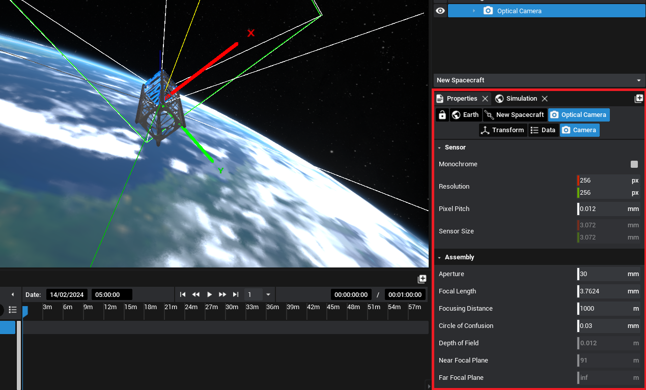
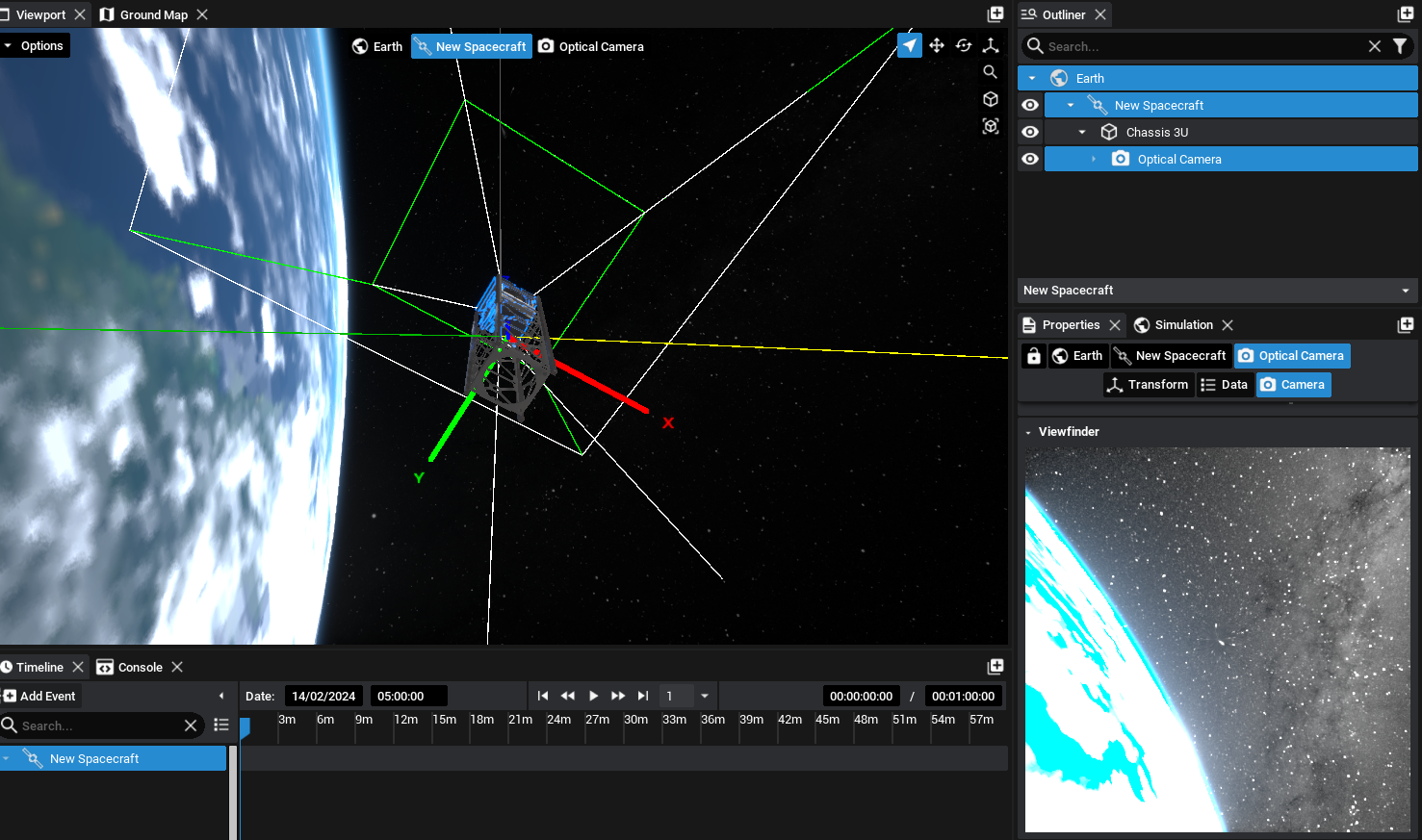
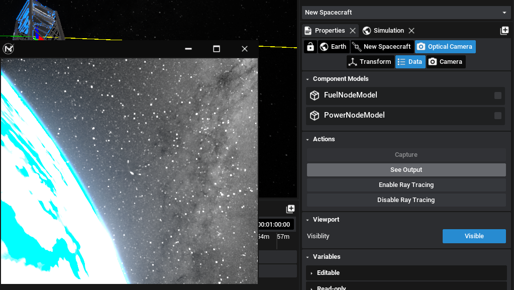
The Properties Panel also includes a live Viewfinder feed from the camera payload and the ability to export an image render to disk. The above optical camera properties result in the below Viewfinder image as the optical camera is pointing away from the sunlit side of the Earth. Capture events have been configured for each of the camera payloads provided in the Inventory to generate an image mid-simulation.
Note
When the Camera is selected in the Properties Panel, the Field of View, Depth of Field Planes and Hyperfocal Planes are drawn to the screen.
Saving Images
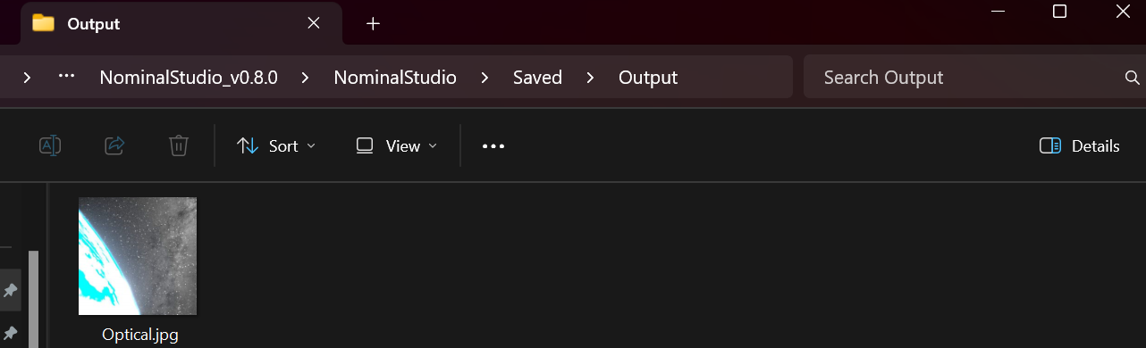
Both during the simulation and when configuring the simulation, the Viewfinder window can be used to export images from the camera to disk and save them into a directory. By default, these images will be located inside the Saved directory of the project. The folder structure can be specified in the Path field, which is defaulted to ‘Output’.
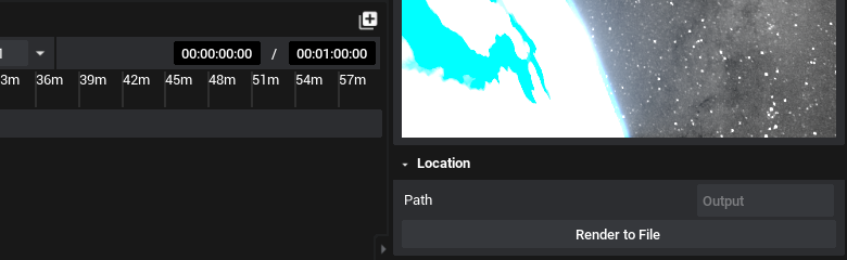
Selecting Render to File will save the image as it is seen then, with the appropriate camera settings, to the directory provided in the format of the camera. This will, by default, be a JPG. Both PNG and EXR options are available and can be configured on the camera properties.
Pop-out Window
Additional to the Viewfinder is a camera widget that can be popped out of the screen. Selecting the Camera and then under the Data view in the properties panel, there is an action to See Output. This will create a new window that can be moved to another location on the Desktop, displaying the view of the camera outside of the panel. It can also be resized and scaled as appropriate.
Provided that the simulation is running, the Capture function can also be called via an action, both from an external action or manually, which will save the state of the image to the saved directory. This functionality works with all types of camera payloads.