Spacecraft: Configuring Components
Configuring the Computer
The Guidance Computer is a ‘smart’ component that can detect the components on the spacecraft and enable flight software pointing based on the components that exist. Select the Guidance Computer and head to component properties.
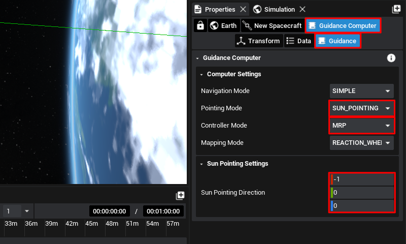
Here, the pointing vectors for the solar panels can be specified. This is important so that the spacecraft knows which side to orient toward the sun. By default, it will pick up on the solar panel vector and apply it here. Set the controller mode to MRP, instead of IDLE so that the computer is not idle during the simulation. The pointing mode will define which direction the primary payload should be pointed towards. With Ground Pointing as the Pointing Mode, specify the pointing vector along the axis the camera is pointing when selected if it is not set already. Next set the pointing mode back to Sun Pointing for the beginning of the simulation and then add the correct pointing vector. In this example, we can see the solar panel is pointing along the negative x-axis.
Note
The guidance computer is a useful component as it hides away the flight software logic. Custom logic can be built in Nominal Editor and exported to Studio if required. Additionally, pointing modes can be changed during simulation time by selecting the component and adjusting the parameters.
Camera
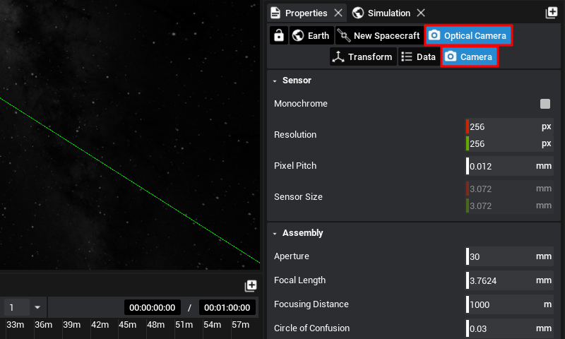
Moving over to the camera next, let’s ensure the settings are reasonable for Earth observation tasks. With the camera selected, go to the camera properties here.
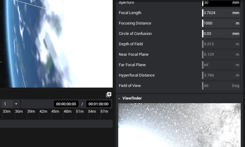
Scroll down to reveal the Viewfinder, in this case, the camera is too bright for making out details on Earth. This can be fixed by reducing the aperture as an example. Make any necessary changes up to your preference and then move on to the next section.
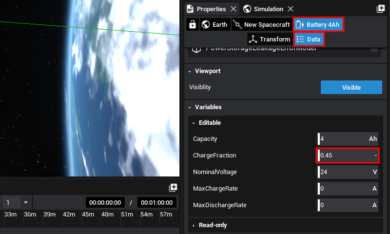
Battery
One last step, select the battery and set its initial charge to a bit below half, at 0.45. The next section covers events for managing the battery level with pointing modes.