Editor: Configuring a Satellite Constellation
Description
This operator guide showcases how to instantiate a Coplanar constellation using the provided utility functions. An example of this is present in the demo found in Orbits/Demo_Constellation. This uses a Walker Delta function to initialize a constellation around the Earth, with spacecraft equally spaced around the orbit.
Defining the Coplanar Constellation
To define the orbit of every spacecraft in the constellation, use the Make Coplanar function. Use the input properties to define the configuration of the coplanar orbit. These parameters are:
- Semi-Major Axis: The osculating semi-major axis of the orbit that will be applied to every spacecraft in the constellation.
- Inclination: The osculating inclination of the orbit that will be applied to every spacecraft in the constellation.
- Omega Ascension: The osculating Right Ascension of the Ascending Node that will be applied to the orbit of every spacecraft in the constellation.
- Omega Periapsis: The osculating argument of periapsis that will be applied to every spacecraft in the constellation.
- True Anom Ref: The starting osculating true anomaly of the reference spacecraft. The true anomaly of every other spacecraft will be equally spaced around the full orbit offset from the
True Anom Refvalue. - Num Satellites: The number of satellites in the constellation.
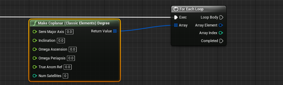
The Make Coplanar function returns an array of classical orbital elements with each element of the array representing the initial state of every spacecraft in the constellation based on the input configuration. This array can be used to instantiate the orbits of every spacecraft in the simulation. The easiest way to do this is to loop through each element in the array and set the orbit of every spacecraft individually.
Defining a Walker Delta Constellation
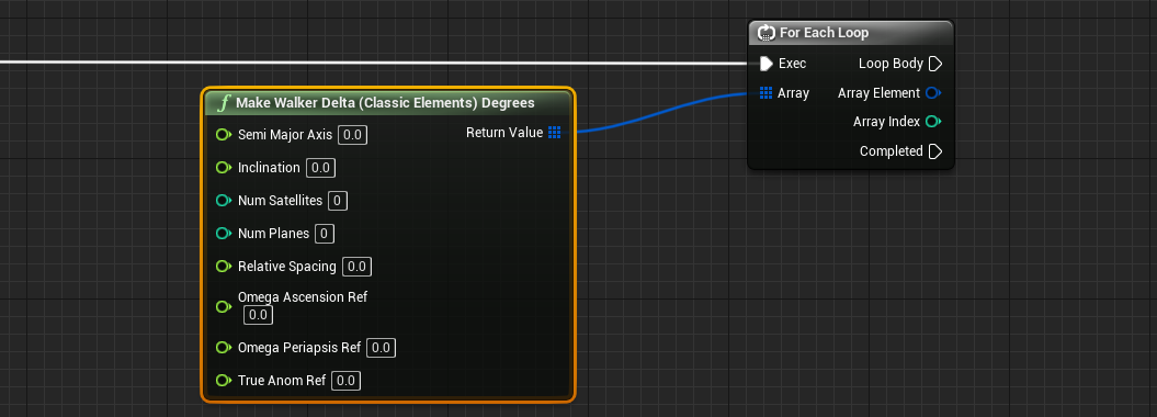
To define the orbits for a Walker-Delta constellation, the same process can be followed but with the function Make Walker Delta function. This will return an array of classical orbital elements, with each element of the array representing the initial state of the orbit. A Walker-Delta constellation is a specific arrangement of multiple communication satellites in a particular orbit. It is designed to provide global coverage and redundancy for satellite-based services, such as telecommunications and broadcasting. The constellation typically consists of a specified plane with satellites spaced equidistantly in each plane. It is defined with the following properties:
- Semi-Major Axis: The distance from the centre of the orbiting planet and the constellation (constant for all spacecraft in the constellation).
- Inclination: The inclination angle of the orbit that all spacecraft and orbiting planes should follow.
- Num Satellites: The number of satellites that should be created. This is not the number per plane, but the number of satellites across all planes with this constellation.
- Num Planes: The total number of orbiting planes that should be created. If the plane is set to two, there will be two types of orbits that the satellites will be across.
- Relative Spacing: The degree of spacing between each of the spacecraft. This can be used as an override when constructing the constellation.
- Ref: These values provide reference values for the planes initialized which will define where the plane and initial starting points of the spacecraft are on the plane.
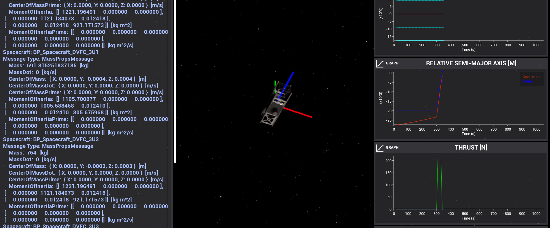
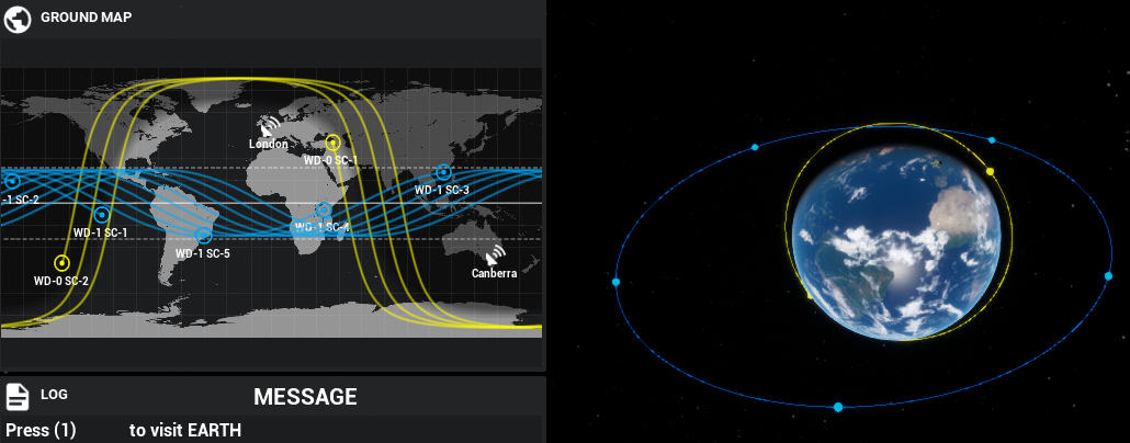
Two constellations initialized with the Walker-Delta constellation around the Earth will look something like the example demo with the constellations.
Setting the Initial Orbit
To set the initial orbits of each spacecraft, create a spacecraft upon every iteration of the for loop by using the Create Spacecraft function. In this case, each spacecraft is initialized with the same input initial rotational state. For this created spacecraft call the Set Classic Elements method and pass as input, the “Array Element” containing the initial orbital elements for the spacecraft in the constellation.

Upon completing the iterations, the initial orbit of every spacecraft will be set. Continue configuring the rest of the simulation for these spacecraft objects as normal.
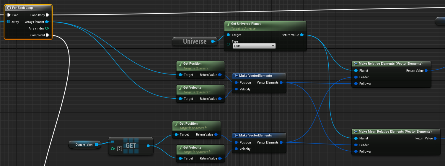
Measuring the Relative Orbital Elements
To calculate the relative osculating or relative mean orbital elements, use the Make Relative Elements function. This function must take as input the reference planet being orbited to complete the conversion of absolute state to mean orbital elements and then to relative orbital elements. This function also takes the Inertial state vector of the spacecraft (Follower) and a corresponding reference spacecraft (Leader) in which its state is being measured relative to. The state vectors of the leader and follower spacecraft can be created by using the Get Position and Get Velocity functions in the spacecraft class.