Editor: Kinematic Rotation Conversions
Description
Nominal provides multiple ways to calculate the rotations of objects within the simulations. Each of these rotation types is used at different points and all have conversions between each of the values. This guide will describe each of these rotation systems, how they work and what they are most useful for. Additionally, it shows how to convert the rotations between each other using the Blueprint functions that have been exposed to do so.
Euler Angles
Euler angles are a set of three angles used to describe the orientation of an object in three-dimensional space. The three angles represent rotations about distinct coordinate axes, typically denoted as roll (rotation around the X-axis), pitch (rotation around the Y-axis), and yaw (rotation around the Z-axis). The ordering of these rotations is crucial, as different orderings can yield different final orientations. This phenomenon is known as gimbal lock, which occurs when two of the three rotations align, resulting in the loss of one degree of freedom. Choosing the correct order is essential to avoid gimbal-lock and accurately represent the desired orientation. Common Euler angle sequences include 1-2-3 (XYZ), 1-3-2 (XZY), and 3-2-1 (ZYX), each specifying a particular order in which the rotations are applied. The choice of ordering depends on the specific application and how the rotations need to be combined to achieve the desired orientation.
For each of the conversion functions that convert an Euler angle to another type or another type to an Euler angle, the order in which the angles are applied is required and the number is used in the function. 12 combinations of ordering with the indexes of 1, 2 and 3, are added to ensure that every combination for the conversions is available.
Note
In Nominal Editor, Euler angles are expressed as a three-part vector and expressed in degrees. The parts associated with them are designated as X = roll, Y = pitch and Z = yaw; each rotation in a clockwise direction about the associated vector.
Modified Rodriguez Parameters (MRP)
Modified Rodrigues Parameters (MRPs) are different representations of three-dimensional rotations, using a three-part vector to describe the orientation of an object. MRPs provide a more singularity-robust alternative to Euler angles. The three parameters, typically denoted as \(q_1\), \(q_2\) and \(q_3\), form a vector that represents the axis of rotation multiplied by the tangent of half the rotation angle. The ordering of the MRPs is also critical, affecting the final orientation. Similar to Euler angles, incorrect ordering can lead to ambiguities in representing rotations. Selecting the proper order is essential for avoiding mathematical singularities and accurately capturing the desired orientation. MRPs offer advantages in terms of numerical stability and avoidance of gimbal lock, making them valuable in applications such as spacecraft attitude control and robotics, where precise and robust orientation representations are crucial.
where \(\mathbf{q}\) is the MRP vector, \(\phi\) is the rotation angle and \(\hat{\mathbf{n}}\) is the unit vector along the rotation axis.
The spacecraft class utilizes MRPs when dealing with the Attitude of the spacecraft. These are the calculations that are done when passing the initial parameters into the attitude value on the spacecraft creation. Additionally, the attitude is also denoted as Sigma. For example, when reading the body states output message, Sigma_BN is the attitude of the spacecraft in the inertial frame.
Quaternion
A quaternion is a mathematical construct used to represent rotations and orientations in three-dimensional space. Unlike Euler angles, quaternions avoid the issue of gimbal lock and offer a concise and computationally efficient way to express 3D rotations. A quaternion consists of a scalar part (real component) and a vector part (imaginary components), often denoted as \(q_0 + q_1i + q_2j + q_3k\). The scalar part represents the cosine of half the rotation angle, and the vector part encodes the axis of rotation scaled by the sine of half the angle. Quaternions can be easily interpolated, concatenated, and normalized, making them particularly useful in computer graphics, robotics, and physics simulations. Their compact representation and algebraic properties make them a powerful tool for working with rotations in a way that is both computationally efficient and avoids some of the pitfalls associated with other representations.
Direction Cosine Matrices (DCMs)
A Direction Cosine Matrix (DCM), also known as a rotation matrix, is a mathematical representation of a 3D rotation. Let \(R\) be a 3x3 matrix representing the DCM, where the columns of \(R\) are the unit vectors of the rotated coordinate system expressed in the original coordinate system. The rotation matrix \(R\) can be used to transform a vector from one coordinate system to another. DCMs have the property that their transpose is also their inverse (\(R^T = R^{-1}\)), and their determinant is always equal to \(+1\), ensuring proper orthogonality and orientation preservation. They are widely used in aerospace, computer graphics, and robotics for representing and transforming orientations.
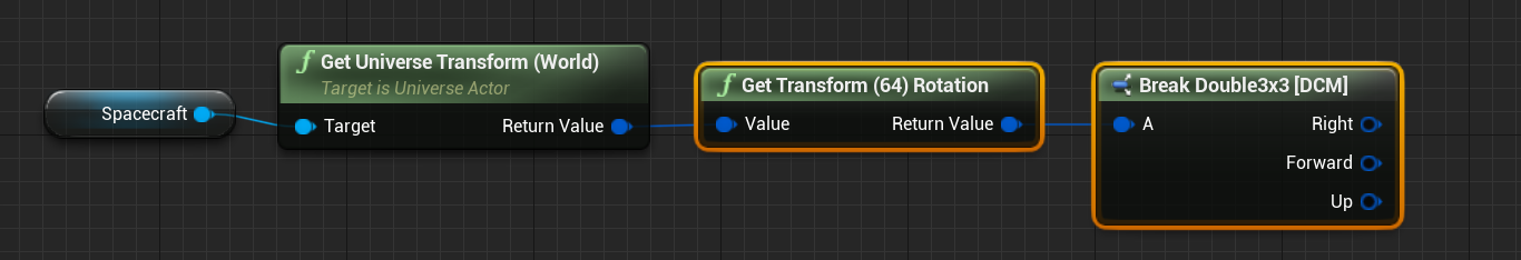
The transform system treats the rotation part as a DCM. Using the Unreal functions to fetch the Universe Transform can fetch the DCM of the spacecraft or other objects (that are of type Universe Actor) in the simulation.
Conversion Functions
For each combination, there are conversion functions between each option. These can be found under the Nominal Systems | Maths | Kinematics category and are static functions on the level blueprint. Every combination of Euler rotation conversion can also be found here.
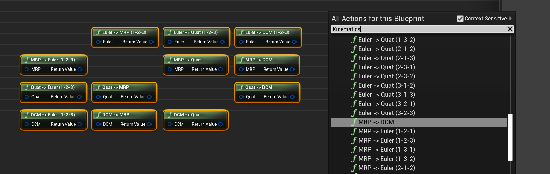
Each of the four types of data has the following data types when converting the data:
- Euler:
FDouble3 - MRP:
FDouble3 - Quat:
FDouble4 - DCM:
FDouble3x3