Editor: Ground Station Pointing
Description
This guide demonstrates how to configure a Ground Station Computer to determine an Access Message for an object in space, such as a Spacecraft, a Gravity Body, or other Ground Stations. The Ground Station Computer is used to store a Software Chain, which takes an input that includes the inertial position of an object and will output an Access Message representing the elevation, azimuth, and slant range between the Ground Station and the targeted object.
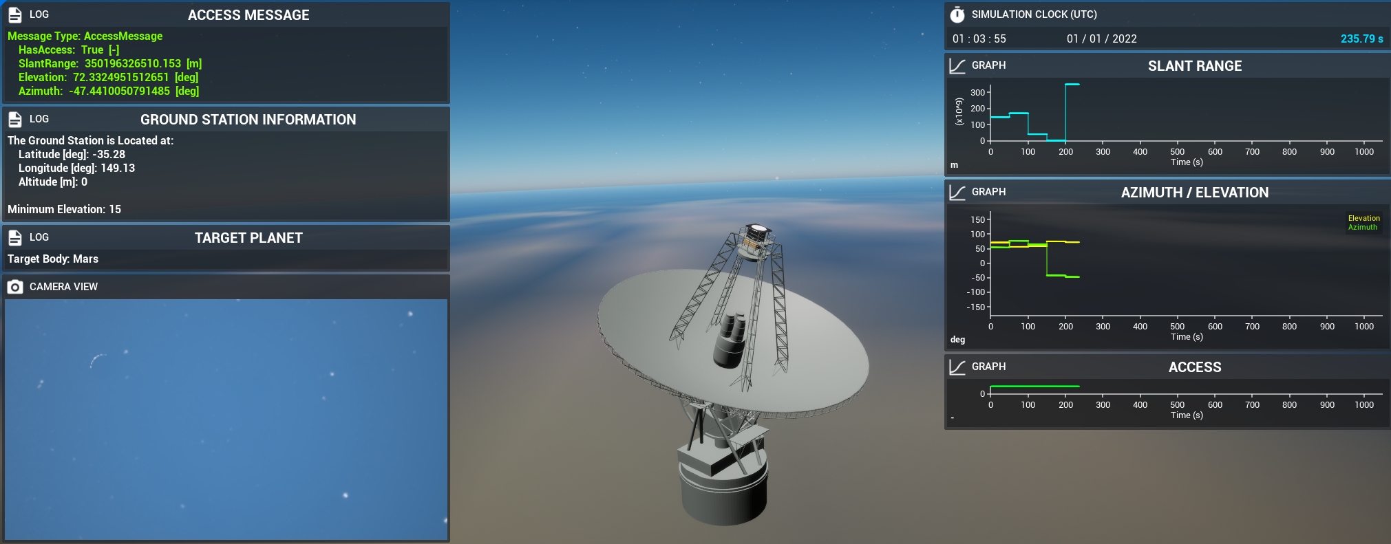
An example scenario for this can be found in Ground_Station/Demo_GroundStationSoftware, where a Ground Station has been created with a rotating dish. A Ground Station Computer has been added and configured for calculating messages from the Ground Station to a planet. The input used for the software chain will be changed every 10 seconds, causing the Ground Station to target another planet.
Creating the Ground Station
The level should be configured to create a Ground Station that is stationed on a Gravity Body such as the Earth. The Ground Station must have the following essential components:
- Ground Station Computer: Used for storing the software components that will convert the input message to an
Access Message.
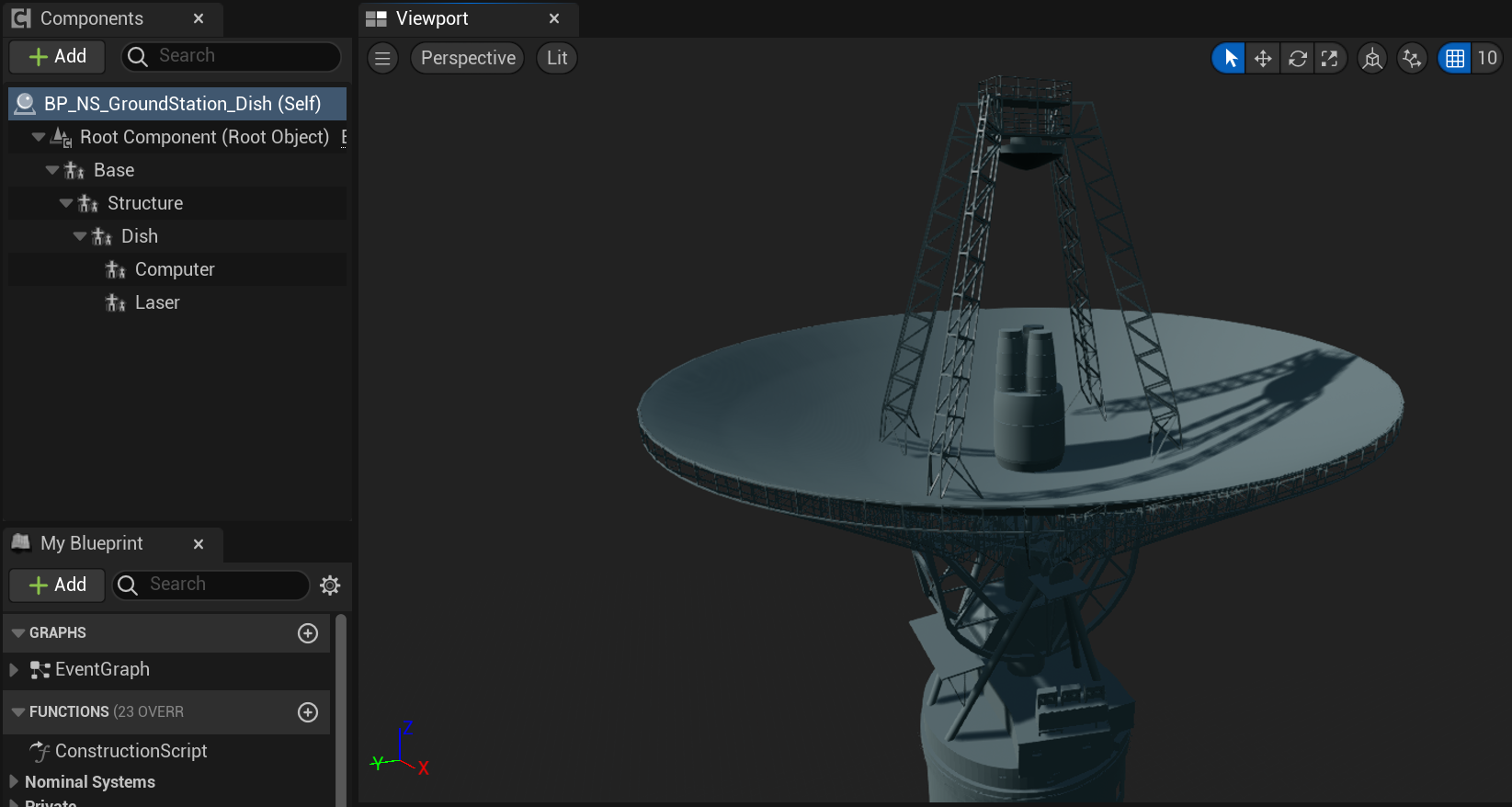
While not required for calculating an Access Message, creating a hierarchy of meshes to represent a rotating dish can help create a visual indication of the Access Message data by providing objects that can be rotated to face the direction of the ground station’s target. The components required for this hierarchy are as follows:
- A
Structuremesh can be rotated around the local up axis (Z). It should be created as a child of the base component in the hierarchy. - A
Dishmesh can be rotated around the local forward axis (X). It should be created as a child of the “Structure” mesh component in the hierarchy.
In this example, the BP_NS_GroundStation_Dish object is used to represent this ground station. However, any ground station object could be used, provided that it has the previously mentioned components attached. The image below displays the Ground Station object used in this example.
Connecting Ground Station Software
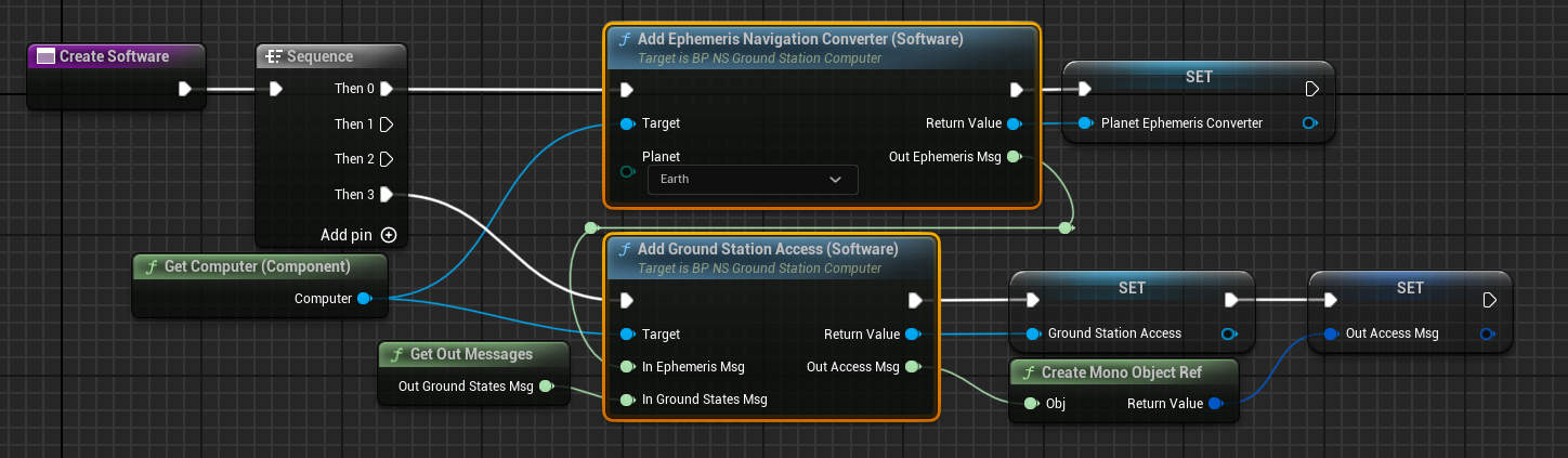
After creating the ground station, software components can be added to the Ground Station Computer to construct a Software Chain. In this example, the software chain consists of two components; the Ephemeris Navigation Converter, and the Ground Station Access software. These components are responsible for converting the planet’s position information into an Ephemeris Message and an Ephemeris Message respectively.
These components are added to the Ground Station Computer using the Add Ephemeris Navigation Converter and Add Ground Station Access functions, which are both defined in the Ground Station Computer Blueprint. For the Ephemeris Navigation Converter software, an enumeration representing the planet you wish to set as the target as input, along with the computer that this software is being added to. For the Ground Station Access software, connect the Ephemeris Message from the Ephemeris Navigation Converter, as well as the Ground States Message from the Ground Station class, as shown in the image below.
If objects other than planets are to be targeted, replace the Ephemeris Navigation Converter software with the relevant equivalent for the object that you wish to track instead. These software components are the Ground Station Ephemeris Converter software for Ground Stations and the Spacecraft Ephemeris Converter software for targeting spacecraft. All of these software components will take input from an object and use it to create an Ephemeris Message, which can be connected to the Ground Station Access software to create an Access Message.
Changing Targeted Object
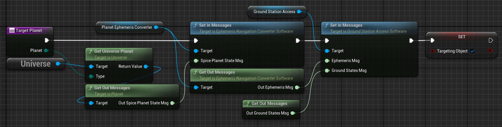
To change the object being targeted by the Ground Station Access software, use the Set in Messages function on the Ephemeris Navigation Converter software (or software equivalent if objects other than gravity bodies are being tracked) and change the input message to the message associated with the new target. This will automatically cause the Software Chain to begin calculating access for the new object.
Rotating Ground Station Dish
If the ground station blueprint has been created to have a rotatable dish that can be faced towards the targeted object, the Access Message calculated by the Software Chain can be used to determine the rotation of the station’s dish required to face the object. In this example, the Ground Station dish will rotate if the Access Message indicates that the object can be accessed by the ground station. If it can be rotated, then the Azimuth and Elevation values can be used to determine the desired local rotations for both the structure, and the dish of the ground station, and the station is then able to apply these rotations to face towards the target.
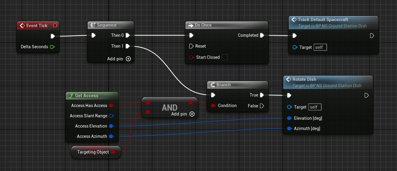
In this example, the Access Message is assessed and rotations are applied in the Event Graph of the ground station itself. However, this could also be performed in a Level Blueprint instead, if preferred.
In this example, the ground station dish is rotated to immediately face towards the desired target. However, the azimuth and elevation values could be combined with other components to apply this rotation over time to better simulate more realistic motion of a Ground Station’s dish.
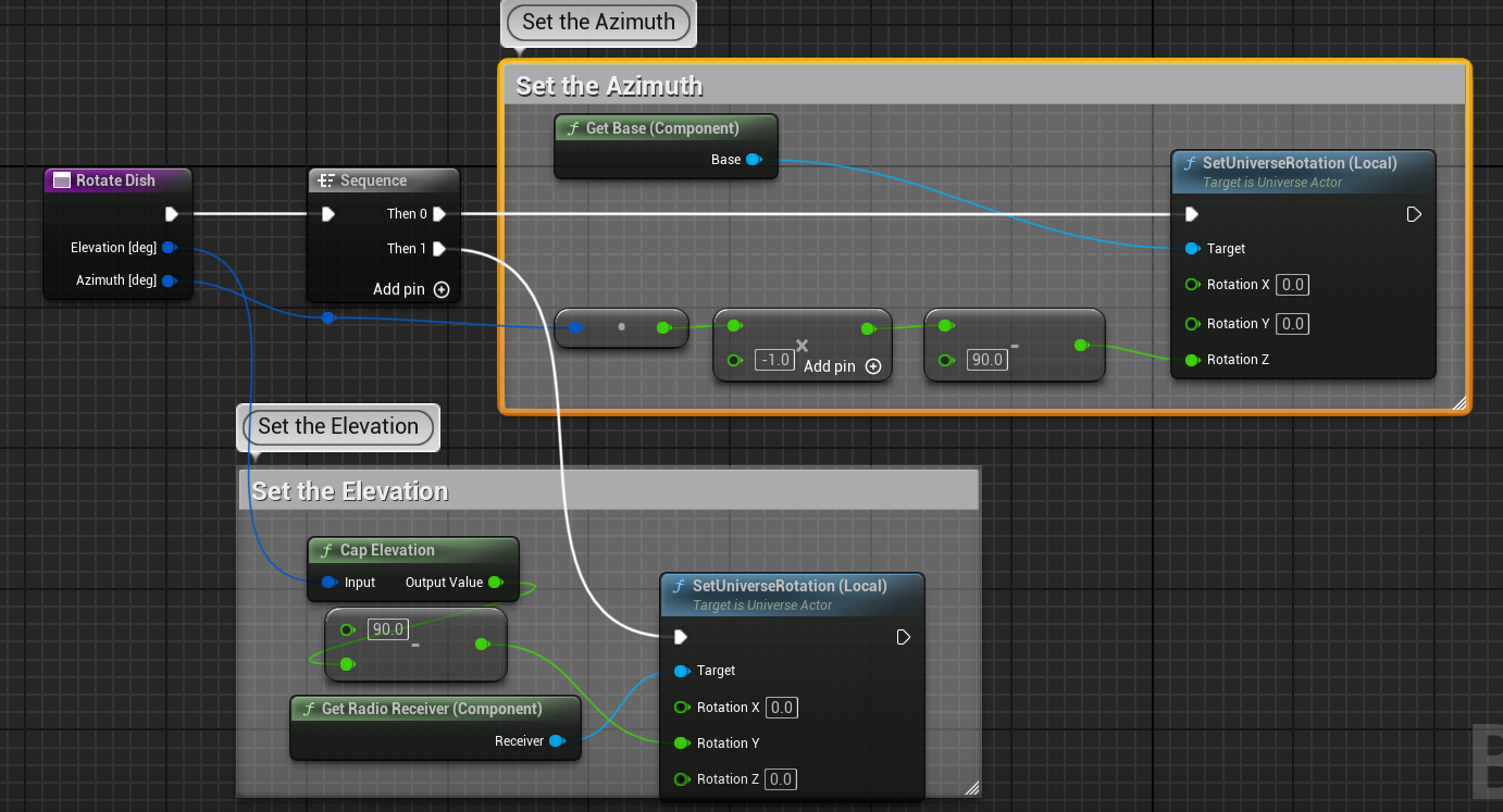
Note
This function rotates the Radio Receiver component around the Y-axis instead of the Dish component. The rotations that must be applied will depend on the orientation of the components within the Ground Station, but the Elevation component should be applied to the child of the “Azimuth” component rotation.