Editor: USB External Integration
Description
This guide will walk through the specifics of using Serial connections, specifically Universal Serial Bus (USB), within Nominal Editor simulations. USB can be used to send and receive data from external hardware. Before starting this guide, it is recommended that users are familiar with the Integrating External Hardware or Software guide and the fundamental principles of USB.
Warning
The functionality for USB functions may depend on valid hardware connections and a valid port that can be opened. As such, the functionality of this feature may depend on the environment in which Nominal Editor is being run. Cloud deployments, for example, may not run USB functions as expected.
Connection and Configuration
The first step for any external hardware integration is to configure and establish a connection. To add a USB connection to an existing simulation, the Open ComPort Blueprint function needs to be called, with the Port Name set to the available Serial Port, and with a matching Baud Rate to the external device serial configuration. The List ComPorts function can be used within Nominal Editor, to return the list of devices to potentially connect to.

Note
The Baud Rate must be the same as the device’s communication rate. If this differs, data may be read incorrectly. A common baud rate is 115200, which is used by a Raspberry Pi device, as an example.
Bidirectional Data Flow
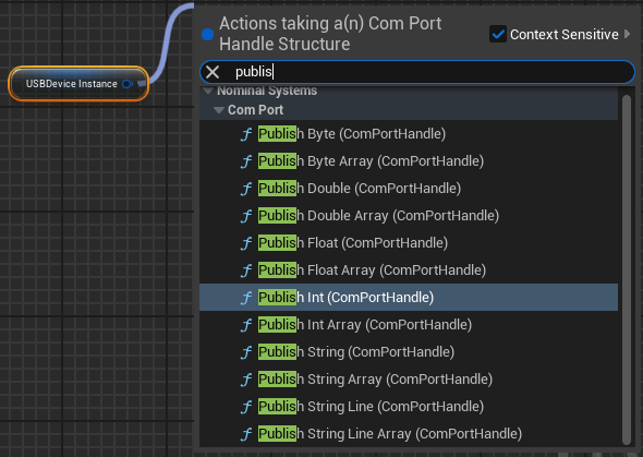
Once connections have been established, data can start flowing in and out of the simulation. To assist in publishing simulation data over USB, USB publish- functions exist for Byte, Double, Float, Integer, String and Line. Array publishing of these data types is also supported.
To receive data over USB, receive functions have been created for each of the USB publish functions.
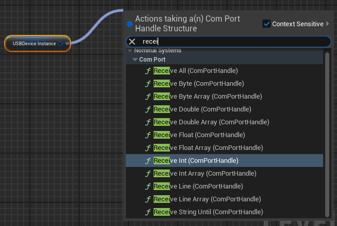
As Receive array functionality only exists for Byte Arrays, an array of Integers can be read from the buffer using the following method.

Note
All Receive functions have a timeout in milliseconds to limit the main thread from locking up if no data is available. It is also advised a check of the amount of data available in the USB buffer, using the NumBytesInBuffer function, is done. This is to ensure that the target number of integers worth of data is available to be read out of the buffer.
Simulations can also be structured to use the USB Blueprint pure functions to trigger certain data flow events, such as reading and decoding messages or only ticking the simulation a single step per received packet. To learn more about synchronizing external hardware and Nominal Editor simulations, refer to the Time Syncing External Hardware guide. Possible Blueprint pure functions that can be used as a part of these triggers are shown below.

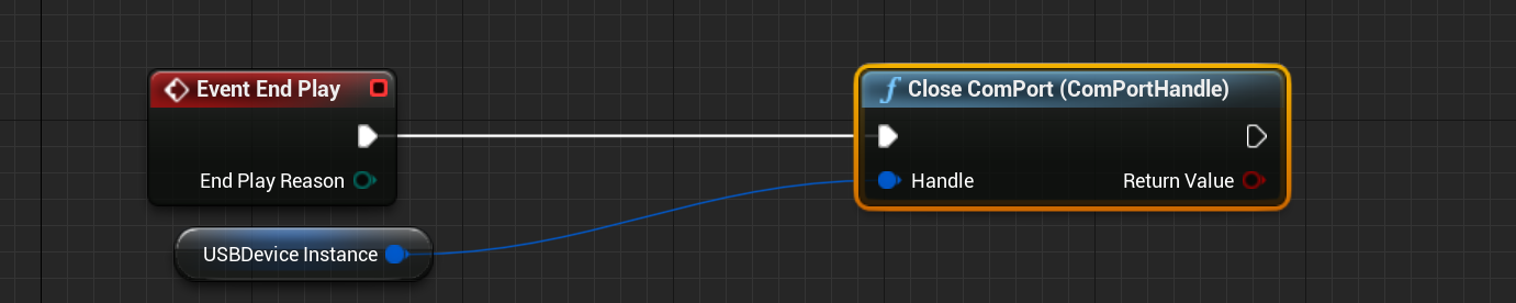
Closing USB Connections
Once a simulation is completed, or if the USB connection needs to close early, the USB Close ComPort function can be used. It is recommended that this function is also called on Event End Play within the level blueprint to ensure the connection is closed and the COM port is freed. Whilst this won’t close the connection cleanly in the event of a software crash, it will create a clean disconnect the majority of the time and is still advised as a backup if the connection is meant to close on a specific instruction received over USB.