Editor: Time Syncing External Hardware
Description
This guide will build a simulation to have Synchronous External Hardware Integration. This approach to External integration can be useful when the Simulation and External Device depend on each other. However, the simulation rate will be reduced due to the codependent link. Nominal Editor could also become unresponsive if care isn’t taken to account for Unreal’s single-threaded nature. It is assumed that the “Integrating External Hardware or Software” guide has been read beforehand and users have at least an Intermediate knowledge of using Nominal Editor.
Warning
The functionality for external hardware depends on a valid hardware connection to the device running Nominal Editor and, depending on the use, a valid port that can be opened. As such, the functionality of this feature may depend on the environment in which Nominal Editor is being run. Cloud deployments, for example, may not run hardware functions.
Instructions
This Operator Guide will use the provided Demo_Syncronous_HwIL_USB stimulation level as a practical example of Synchronized External Integration. In this Demo, an External Flight Computer is emulated via an Arduino Microcontroller that also models Reaction Wheel power consumption based on received reaction wheel data. The emulated Flight Computer determines if the spacecraft should be in NADIR or SUN Pointing modes based on received Battery data.
Connection Initialization
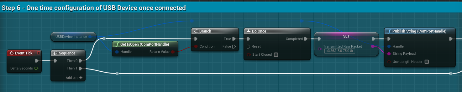
During the Begin PlayEvent, a connection to the Arduino Microcontroller must be configured and opened. Specifics of which are available in the “USB External Integration” Operator Guide. Once the USB Connection has been established, the Emulated flight computer needs to be configured. In this example, a one-time packet is sent that contains parameters for the Reaction Wheel power consumption model and required battery charge fraction thresholds for the Flight Logic. This is shown in the below screenshot.
Data Flow
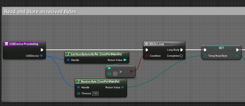
To prevent the Nominal Editor from becoming unresponsive whilst communicating with synchronous external devices, the flow of data needs to be structured to occur over multiple rendered frames. Therefore, it is advised to use reasonable Timeout values in receiving values and to restrict the use of Loops. In the below example, a timeout of 100 milliseconds is used in a while loop that only runs when there is data to be read in from the Serial buffer. This prevents the USB Device Processing function from hanging for a complete packet and locking the rendered frames.
Simulation Tick
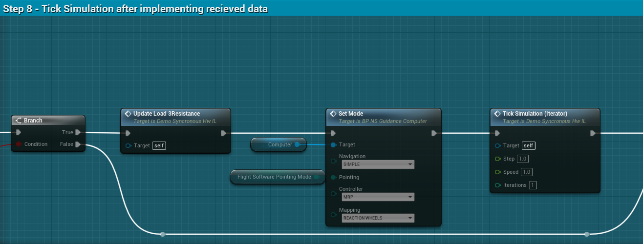
In the referenced demo, the external hardware device only sends back a single packet type. Therefore, whenever a new packet is received, the Nominal Editor needs to complete any updates based on the received data and tick the simulation. In the example shown in Step 8 below, the reaction wheels simulated power consumption, and Satellites Pointing Mode need updating before the Tick Simulation function call. As this is a synchronized hardware integration simulation, Nominal Editor only executes a single step instead of the several per visualized frame of the other provided demos.
If the packets are received from multiple devices or multiple packet types can be received, additional logic is required to determine when to tick the simulation. The simulation step could occur once a packet has been received from every connected device OR only when a Tick Simulation packet has been received.