Editor: On-Board Storage
Partitioned Storage Units
The Partitioned Data Storage component acts as a simulated hard-drive for storing data on an object. This component works with spacecraft and ground stations and is able to store, at its lowest form, raw binary byte data. Because this is a simulated storage system, any bytes stored in the unit will be stored in RAM. As such, storing large amounts of binary data in the unit is unadvised. Nominal Systems have provided some sample storage unit options, such as the BP_NS_DataStorage, which is configured with the following parameters:
- Name: A unique name lookup that is used for mapping commands and data to the storage via the
Operation Computerif required. The name can be left blank if functionality is limited. - Max Memory: The maximum amount of bytes that the storage unit can store. This is capped at 2GB per storage unit.
- Chunk Size: The total number of bytes stored in each chunk. Chunks are useful for storing clumps of data and are optimized in that new chunks are only allocated to RAM when required.
- Clock Message: This is an input message that can be useful for storing timestamps of data to a CSV if required. The
Out_ClockMsgcan be found on a computer provided the time has been set by the user. - Computer Status Message: This is an input message that can be useful for powering down the storage unit if the computer shuts down. The
Out_ComputerStatusMsgcan be found on the computer (of any type).
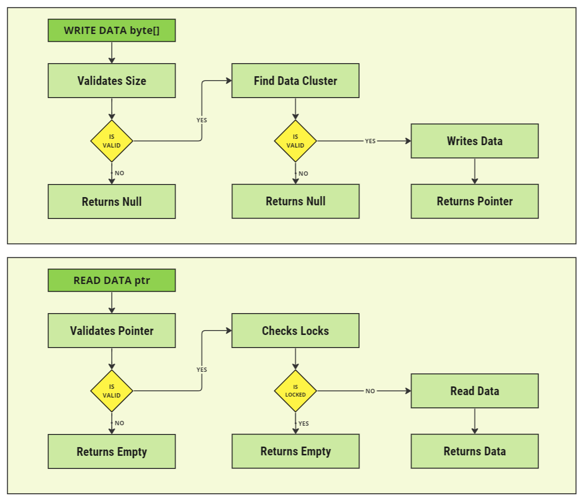
When writing data, the partitioned data storage unit will follow the flowchart below when deciding how to write and read the data correctly from the virtual storage.
Writing Data
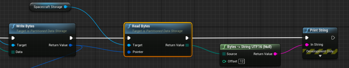
Data can be written to the storage unit using the Write Bytes function. This will attempt to write an array of bytes to the storage unit. When writing the data, a Data Pointer is returned.
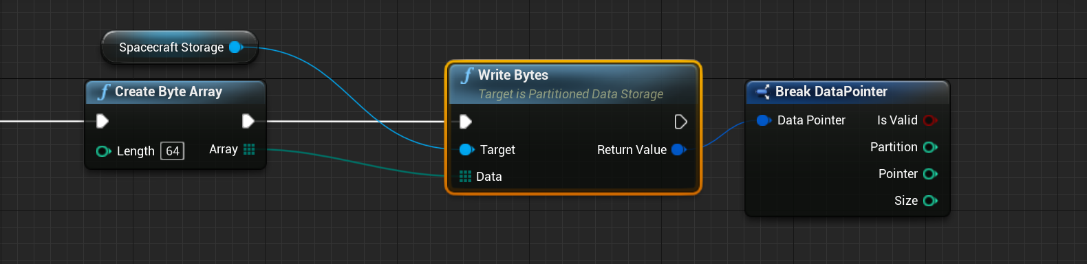
Regardless of the data that is stored, a data pointer is returned. The data pointer is the reference to the bytes and is able to retrieve the data from the storage system at a later point in the simulation. It is a structure that contains four pieces of information:
- Is Valid: A flag indicating whether the data was written correctly and did not have any errors writing the byte data.
- Partition: The chunk index for where the data was written in the data storage unit. This starts at 0 and increases as data begins to fill up.
- Pointer: The starting index within the chunk partition that the bytes are written from. This starts at 0 and increases as the chunk begins to fill up.
- Size: The number of bytes that are stored within the partition from the write action.
Warning
Data is written into chunks within the storage system. If the size of the data to write exceeds the maximum chunk size, then the data will not be able to be written. Data does not overflow between chunks. Consider increasing the chunk size if this is required. However, increasing the chunk size will allocate more of the data to RAM virtual memory when running the simulation.
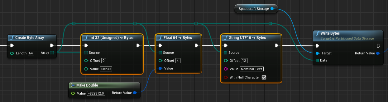
Bytes can be written with custom packets of varying data in mind. For example, writing some integer, float and string data to a byte could look like the following, taking in the byte array as a reference. More information on how to write and read byte data from a binary byte array can be found in the guide Editor: Byte Array Messages.
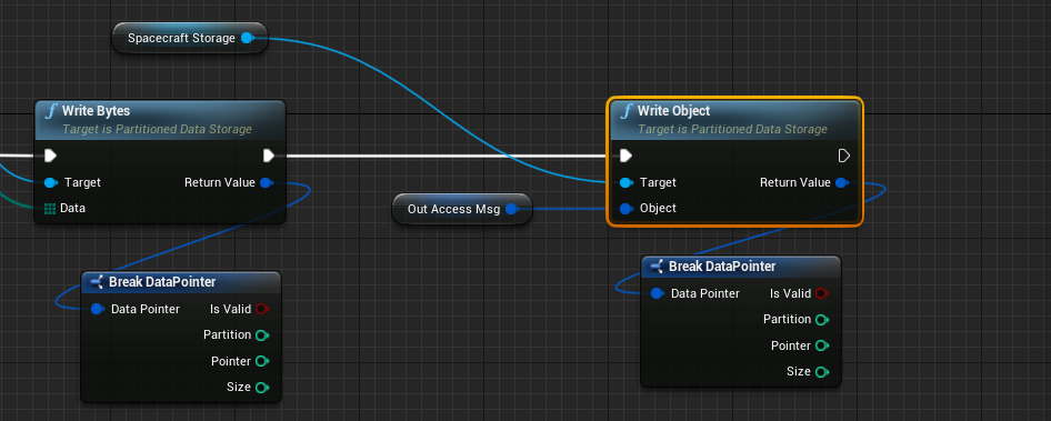
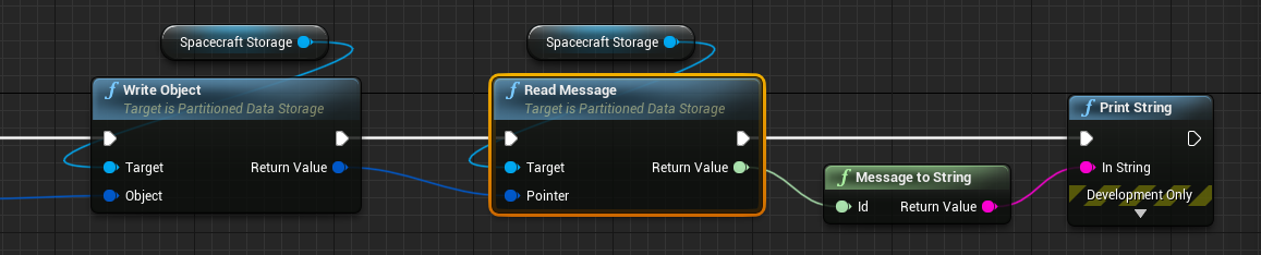
Additionally, messages can be written into the storage system. Messages are serialized entirely to byte data using the raw payload of the message and the type of message. The messages are copied and are not tracked over time. As such, writing a message into the storage system will make a copy of the data. The data within the storage system will not change if the data in the message changes later. This can be done using the Write Object method and passing in the Mono Object reference of the message. More information on how to use messages and mono objects can be found in the guide Editor: Using Messages.
Reading Data
When writing data, a Data Pointer is returned. To read data from the storage system, the pointer must be passed to the storage system and data will be returned. As an example, using the write code above, the text from the byte data can be returned from the storage system.
A similar process can be followed when reading messages from the storage system. Instead, use the Read Message function which will construct a new message from the data within the storage system and return the ID of the message from the function.
Checking Memory
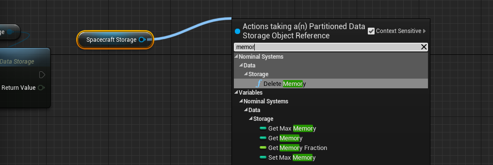
The storage system is able to compute the total memory used within the unit. Using Get Memory, the total number of bytes allocated with memory is calculated. This is calculated as the sum of used bytes within all used chunks. Unused bytes within chunks and unused chunks will not be counted towards this total.
Error Models
There are a few different error models that can be applied to the storage unit for more realistic data effects. This can be used to model realistic situations and for testing out software looking for corrupted data. Each of the models can be enabled by calling it from the storage object.
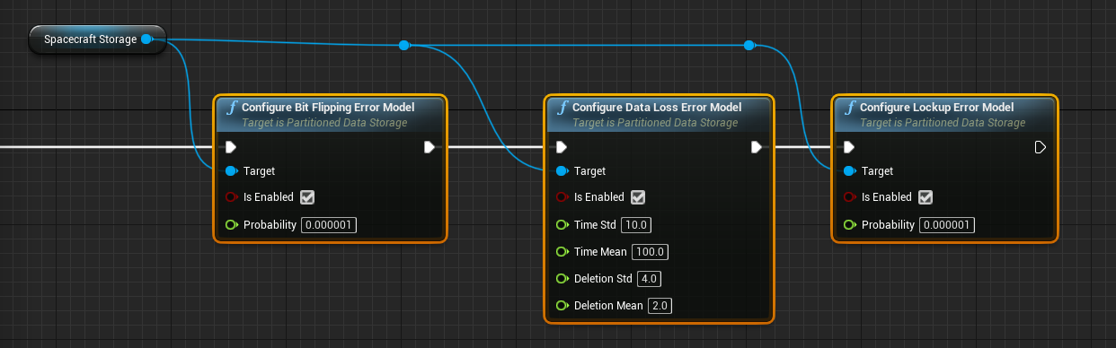
- Bit Flipping Model: Provides a probability that a random bit within the storage system will flip from 0 to 1 or vice-versa. This will flip a single bit and the probability is the chance that each byte contains a bit that will flip every simulated second.
- Data Loss Error Model: Provides a probability that a random amount of bytes will be deleted (reverted to zero) after some time. The
Timeparameters define the length of time between events and theDeletionparameters define how many bytes are deleted. - Lockup Error Model: Data systems are allowed to be locked. If the data is locked, it cannot be accessed unless the data is unlocked. This provides a probability that a specific chunk of data is randomly locked up.
Note
Data storage systems do not have any complex functionality apart from reading and writing. They cannot keep track of variables or export large amounts of data. This is the job of the Data Storage Manager, a software model that can be attached to a storage unit.