Editor: Inter-Satellite Laser Link
Description
Laser-based communication is a growing alternative to traditional radio-frequency (RF) communication and is a simulation capability in Editor. This tutorial focuses on using the laser payload transmitter and receiver components to establish communication links. The Nominal Editor Laser Payload demo is referenced in this guide and is a provided example of spacecraft-to-spacecraft and spacecraft-to-ground communication systems. The demo can also be configured to include the laser payload optical alignment error model.
Configuring Lasers
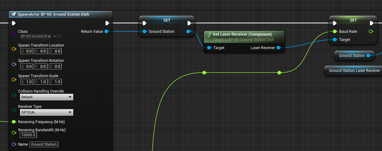
Similar to the other demos, the first step is to spawn and configure the entities within the simulation. For the referenced laser payload demo, this requires spawning the ground station to act as a laser receiver. The ground station is configured as normal but with the Receiver Type set to OPTICAL to configure the laser receiver on the provided BP_NS_GroundStation_Dish asset. The Frequency and Baud Rate of the laser receiver also need to be configured.
Note
For communication to be valid, the transmitter’s frequency must be equivalent to the receiver’s frequency. The receiver will also have a bandwidth that can be specified that enables data with a slower communication speed to also be propagated, should the frequency of the transmitter be within the desired range.
Flight Software
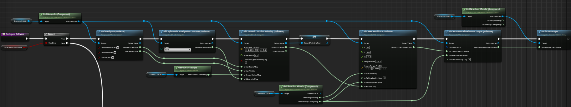
Following the ground station configuration, the main spacecraft for the demo is also configured. The main spacecraft can be configured to point at the ground station or a second spacecraft based on the state of the Point At Ground Station flag, loaded on the level blueprint. When Point At Ground Station is enabled, only the main spacecraft is spawned and configured to point at the previously spawned ground station. The specifics of the spacecraft software used are similar to the software chain deployed in the “Editor: Ground Location Pointing Chain” guide.
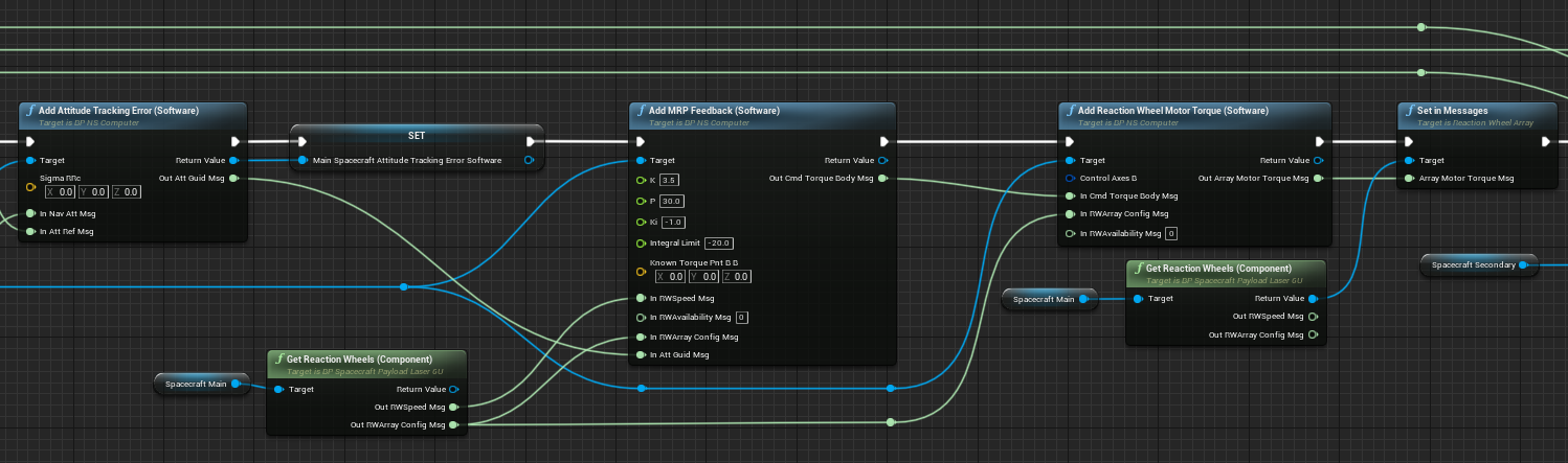
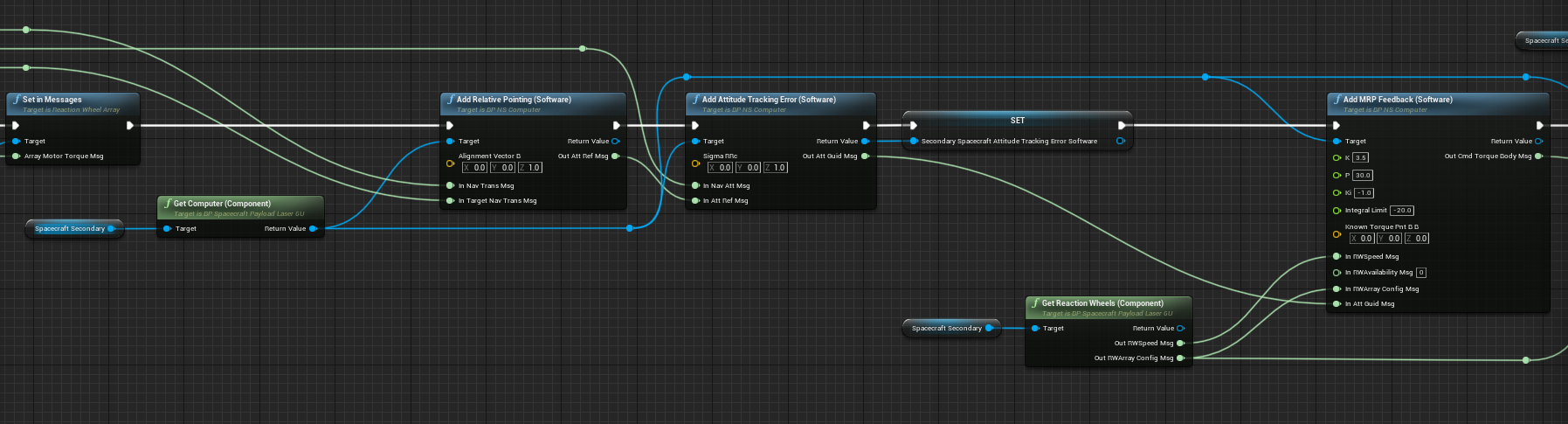
When the demo is configured to show a spacecraft-to-spacecraft laser link, an identical spacecraft is spawned in a trailing orbit. Both spacecraft are configured with a software chain to point the laser transmitter of each spacecraft to the other spacecraft's receiver. As the software chains for both spacecraft are intertwined, it is easier to configure them at the same time, the following screenshots show this process (with overlap)

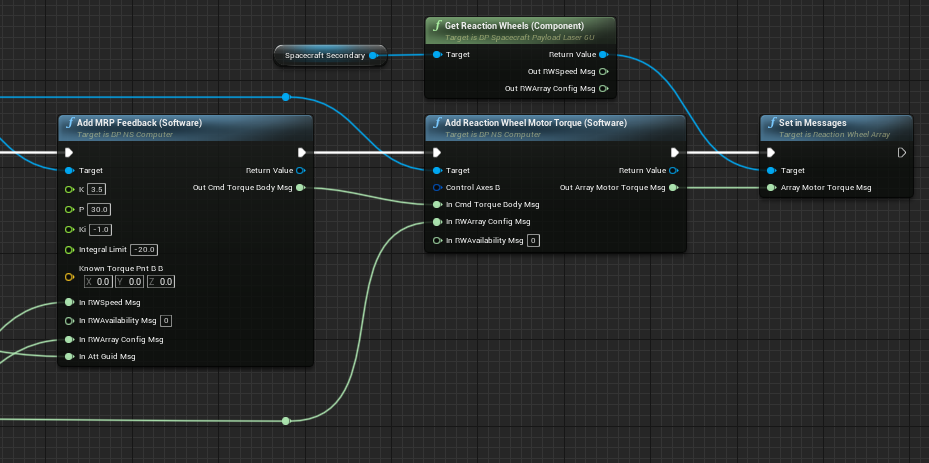
Laser Models
The laser payloads of both spacecraft are also configured, with the only variation being to swap the transmitter and receiver frequencies. As Nominal Editor draws a line between connected Laser Payloads, the colour of that line is set by the connection frequency to help differentiate between different laser links.
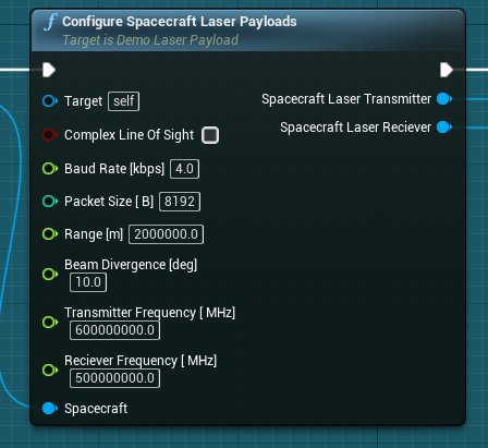
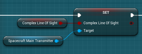
The main spacecraft laser transmitter can also be configured to use the Complex Line of Sight. This flag replaces the backend communication link software with an Unreal ray-cast. This allows for the mesh of other simulation objects to break the communication link, should an object obstruct the link. RF is typically unaffected by this form of interference, while optical light is blocked.
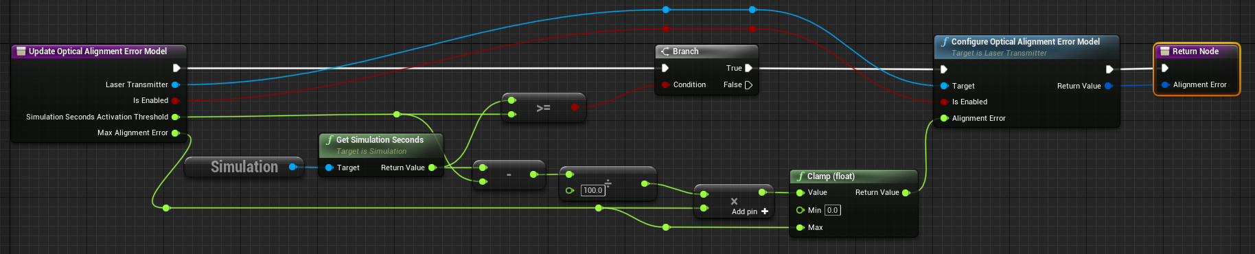
The implementation of the laser transmitter Optical Alignment Error Model can be enabled. This model applies a random angle offset to the laser payload’s emitter and it is configured to have a maximum offset of 5 degrees (in this demo) and is only active after 300 seconds of simulation when enabled in this referenced demo.
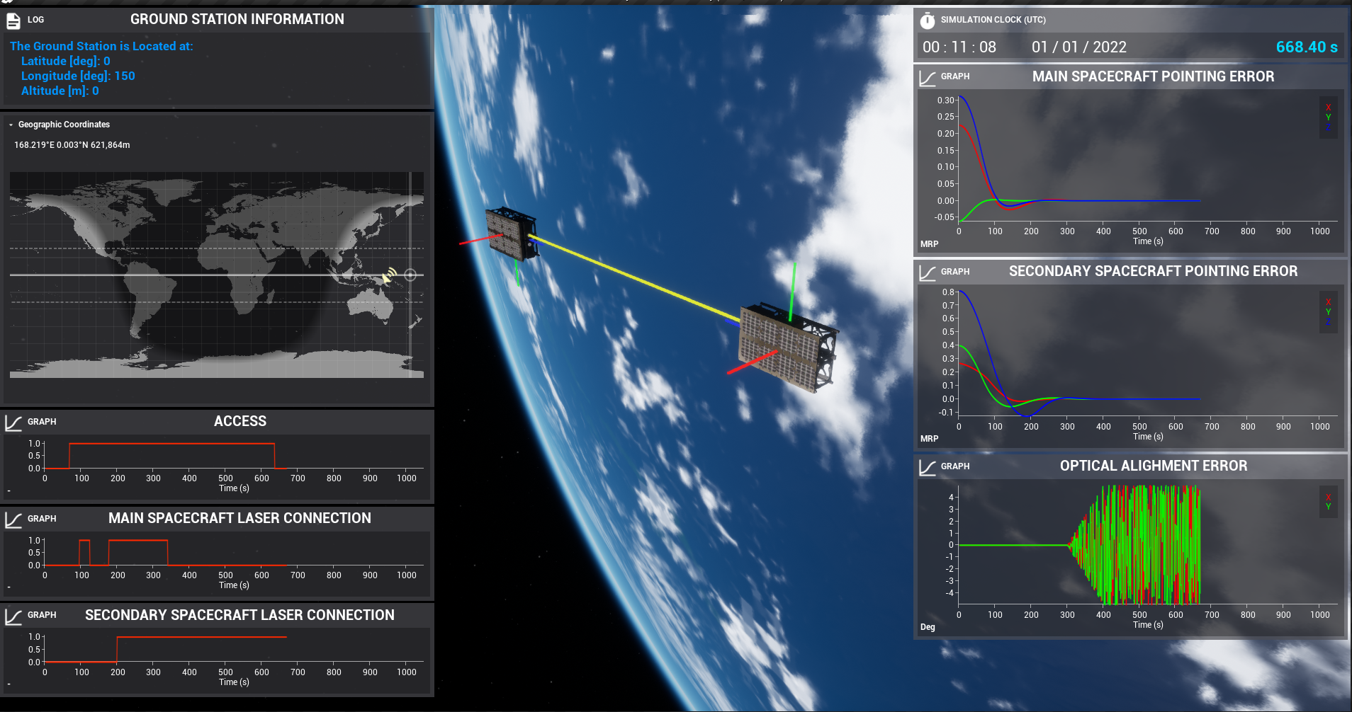
Demo
In the default configuration, the referenced demo is of a spacecraft-to-spacecraft laser link using the Complex Line of Sight backend solution and with the Optical Alignment Error Model. At the simulation timestep shown, the spacecraft has just left the access range of the ground station, with the error model being disabled. As the secondary spacecraft laser transmitter isn’t affected by the error model, its laser link is still connected correctly.
Note
Since the lasers are a form of optical light, debug lines are drawn to show the connection between the laser link. The colour of the line is equivalent to the approximate colour associated with the frequency of the laser, provided it is within the optical light range of 400 - 790 THz.