Editor: Adding a Custom RF/EM Signal Pattern
Description
RF and EM Signatures: The term 'RF pattern' encompasses the structure of both Radio Frequency (RF) and Electromagnetic (EM) signals, thoroughly analysed in both the time and frequency domains. This analysis provides crucial insights into the modulation scheme, frequency content, and spatial properties of signals. Various factors, including interference, noise, fading, and multipath propagation, can influence both RF patterns and EM signatures. The examination of these patterns is vital for applications such as signal detection, modulation recognition, and interference mitigation. This comprehensive approach contributes to the enhancement of wireless communication systems and signal-processing techniques. Integrating RF patterns and EM signatures with antennas in simulations elevates their fidelity, enabling more accurate assessments of radio transmissions between transmitters and receivers.
Generating the RF Pattern Look-Up table
The RF Pattern look-up table would be generated using any third-party RF pattern generator opted by the user. A key assumption of the RF pattern is that it is radially symmetrical about the pointing axis. The lookup table should be generated in .csv format. An example CSV file could look like the following:
Angle, Db Loss
0,0
1,-1.4
2,-5.4
3,-12.2
4,-21.8
:   :
:   :
:   :
356,-21.8
357,-12.2
358,-5.4
359,-1.4
The angle is defined as degrees from a range of 0 to 360 degrees. The second column defines the signal loss (in decibels) associated with the angle.
Note
The angles must be increasing and should already be in order. There may be errors or issues in the RF pattern if the order is not increasing.
The signal strength is a function of angle. This is defined by the angle from the forward vector of the physical component or antenna to the other physical component or signal source. An angle of 0 degrees will indicate the antenna is directly in line with the targeted signal, while an angle of 90 or 270 degrees will indicate it is perpendicular to the targeted vector.
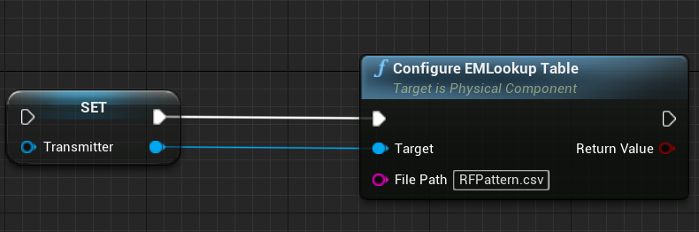
Configuring the RF Pattern
The RF Pattern can be configured to the transmitter or receiver using the Configure EM Lookup Table function as follows. The file path can either be the full path to the file or just the name of the file. The name of the file must be relative to a mapped file point. It is suggested that the file should be placed in the directory Content/Nominal/Data. The return value will output a success from the lookup.
Note
A custom EM signature can be attached to a physical component using the above steps.
Once configured the component will have the appropriate pattern and the signal strength of the EM sensor will be updated depending on the angle between the two objects.