Editor: Using the Guidance Computer
Description
The guidance computer is a subclass of computers that allows the user or software to change the pointing and flight software modes during runtime in the simulation. This can allow the spacecraft’s task to be changed during the flight. The guidance computer is designed to be a ‘plug and play’ device, working straight out of the box with no configuration required. This guide shows how to add the computer to the spacecraft and how the flight chains work.
Adding the Computer
The computer can be added to the spacecraft in two ways; adding to the spacecraft blueprint or spawning in the level blueprint. In this example, we will be spawning via the level blueprint, just to show off the public variables on-spawn, but there is no preferable method for adding the component to the spacecraft. The component can be added using the SpawnActor method and selecting the BP_NS_GuidanceComputer.
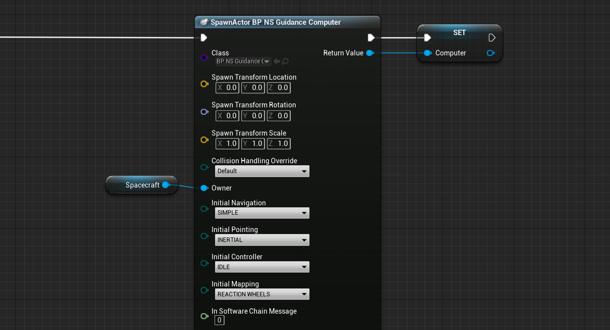
The guidance computer has several spawn parameters; four of them being software mode enumerations and the last being a software chain message. Although the software chain message can be configured, using the enumerations is easier and can perform the same actions for changing pointing modes.
Software Modes
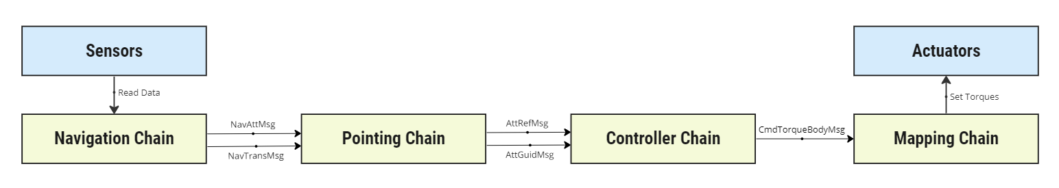
Four sets of software modes are used to create a flight software chain onboard the guidance computer. Each chain type has a specific purpose and the chains can be added together to perform a full software stack. These are:
- Navigation Chain
- Pointing Chain
- Controller Chain
- Mapping Chain
Each chain can consist of one or many software (or interface) modules and there can be many different chains per chain category. However, each chain within the category must have the same input and output messages to connect with the interface between chains.
Changing the chain selection for each chain type can be done with the enumerations, and each category has a different number of chain options to select from. By setting the Initial values when spawning the guidance computer, the starting software chain can be selected and executed on the spacecraft. More documentation on how each of the software chains works and their use cases can be found in the Guidance Computer Technical Manual document.
Updating Software Modes
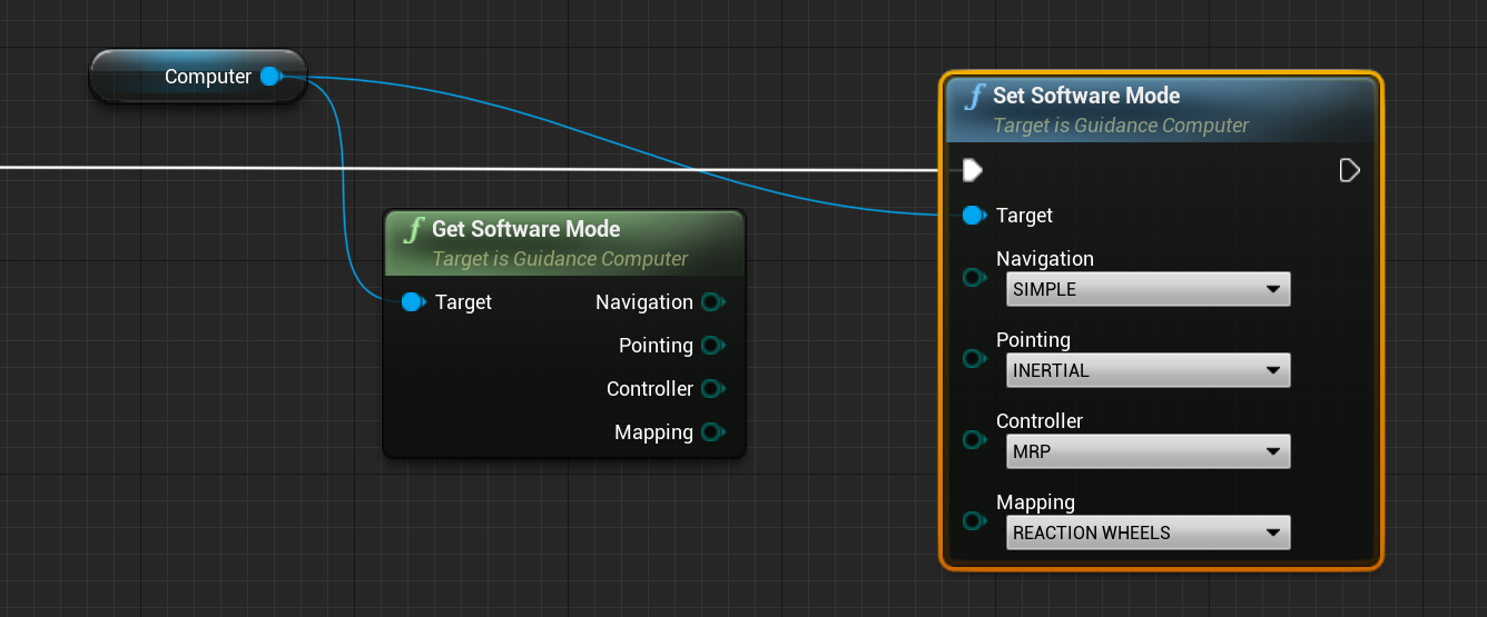
Software modes can be set during runtime when a simulation is running already. The current software modes can be fetched from the guidance computer using a blueprint function and the modes can be set at any point during the simulation. These methods are the Get Software Mode and the Set Software Mode respectively. Each one allows for the selection of each of the four software chain types.
Warning
NOTE: By default, the controller mode will be set to IDLE. This will not adjust the reaction wheel torques. To change this, select the MRP controller mode to ensure that the actuators are used and the pointing algorithms start.
Idling
The guidance computer can idle the spacecraft, which will disable the reaction wheel or other actuators from applying torque on the spacecraft. The Idle Controller Mode can be found by adjusting the controller software chain type from MRP to IDLE. This will disable the commands coming from the controller into the actuator and ensure that no torques are applied. This will not stop the spacecraft from spinning if it is already spinning, but it will prevent the attitude rate from changing due to internal torques.
Configuring Chain Parameters
Each software chain has several configurable parameters that can be adjusted on the guidance computer. By default, a standard selection of parameters is chosen for initializing the software chains. However, if the user prefers to use alternative parameters, they can be adjusted using the Configure methods in Unreal.
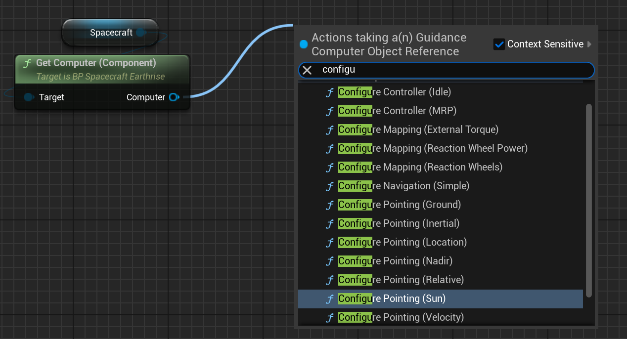
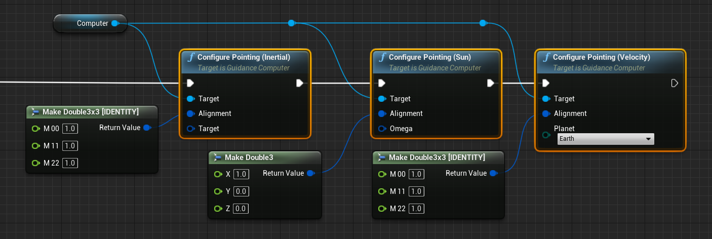
Each software chain that is available across the modes has a dedicated configure method and the parameters exposed in each method may be different. For example, each of the six pointing chains has a parameter called Alignment, which specifies a non-default alignment vector or matrix (depending on the flight software) to align the pointing direction in. By default, leaving these values as a zero vector or a zero matrix will result in the default alignment vector not being overridden. These default values are dependent on the chain but are often using a camera or solar panel payload that exists on the spacecraft already.
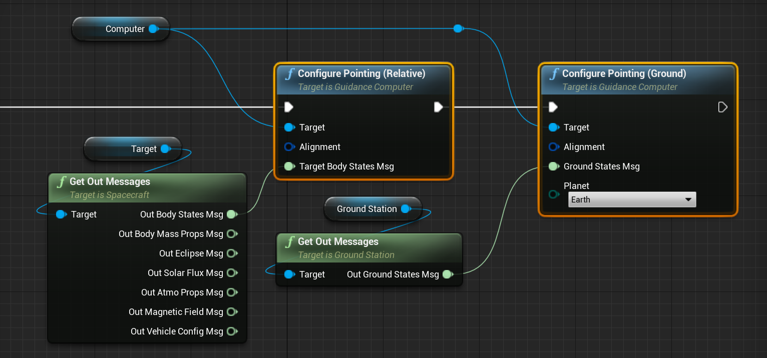
Some of the chains, such as the relative pointing and ground pointing chains require an input message for the software to work. These are the target spacecraft’s body state message and the ground station's state message respectively. These messages can be pulled from the objects using the Get Out Messages function. For example:
Changing Modes with Key Presses
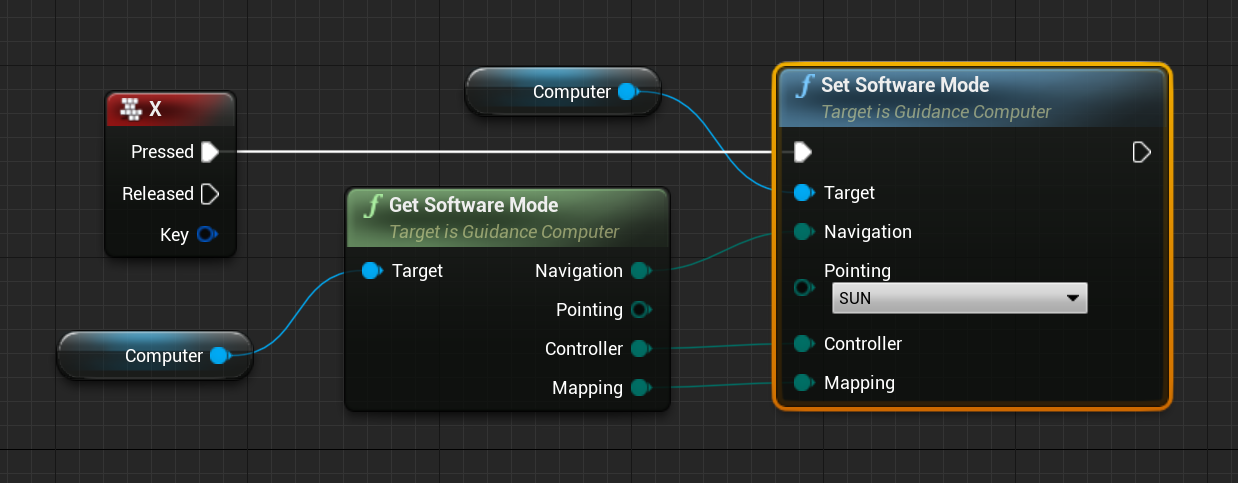
Using the Level Blueprint, button key presses, or events, can be mapped to changing the software modes on the guidance computer. For example, to change a particular software chain type, without adjusting the values on the other software chains, a combination of the get and set software mode functions can be used, ensuring that the other modes are unchanged by the event. In the case below, when the X button is pressed during the simulation, the mode will change to sun pointing, but all navigation, controller and mapping modes remain the same.
Output Messages
Each of the software chain interface messages is exposed to the guidance computer on the level blueprint. They are:
- Navigation Translation Message
- Navigation Attitude Message
- Attitude Reference Message
- Attitude Guidance Message
- Command Torque Body Message
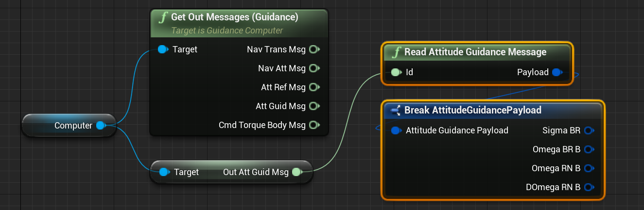
Each of these messages is required for one of the chain types to use or output. To access these messages, use the Get Out Message method or the individual Get Out [MESSAGE] variables on the computer.
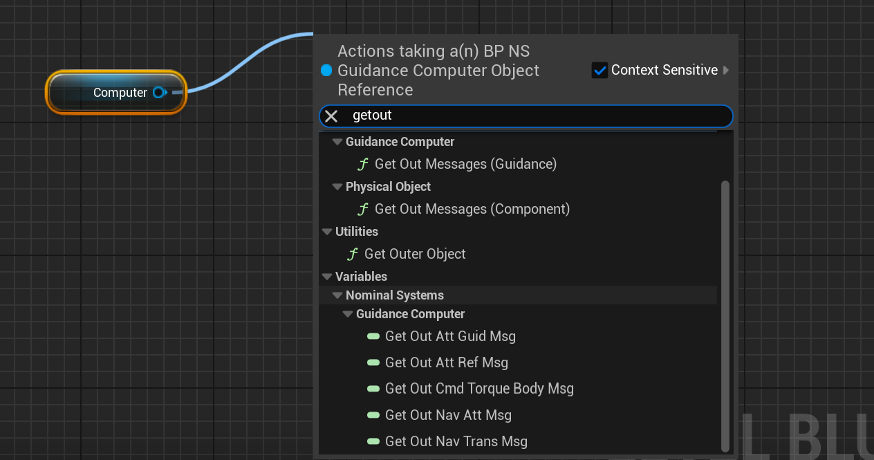
For example, to get the error between the reference frame and the alignment frame that gets fed into the feedback controller, either the Get Out Att Guid Msg or the Get Out Messages method can be used.