Editor: Ground Pointing Chain
Description
This guide showcases how to create a ground-pointing chain on a spacecraft. This chain is designed to direct a payload’s normal direction in the direction of a ground station located on the surface of a body in inertial space. This is commonly used for communication simulations between spacecraft and a ground station network. The ground stations can be located on any celestial body, including the Earth and the moon, and with any latitude, longitude or altitude coordinate.

This example scenario can be found at the Data/Demo_DataNetwork level. It uses a reaction wheel array to orient the spacecraft's attitude to align the antenna in the direction of another spacecraft, allowing for communication of data flow.
Creating the Spacecraft
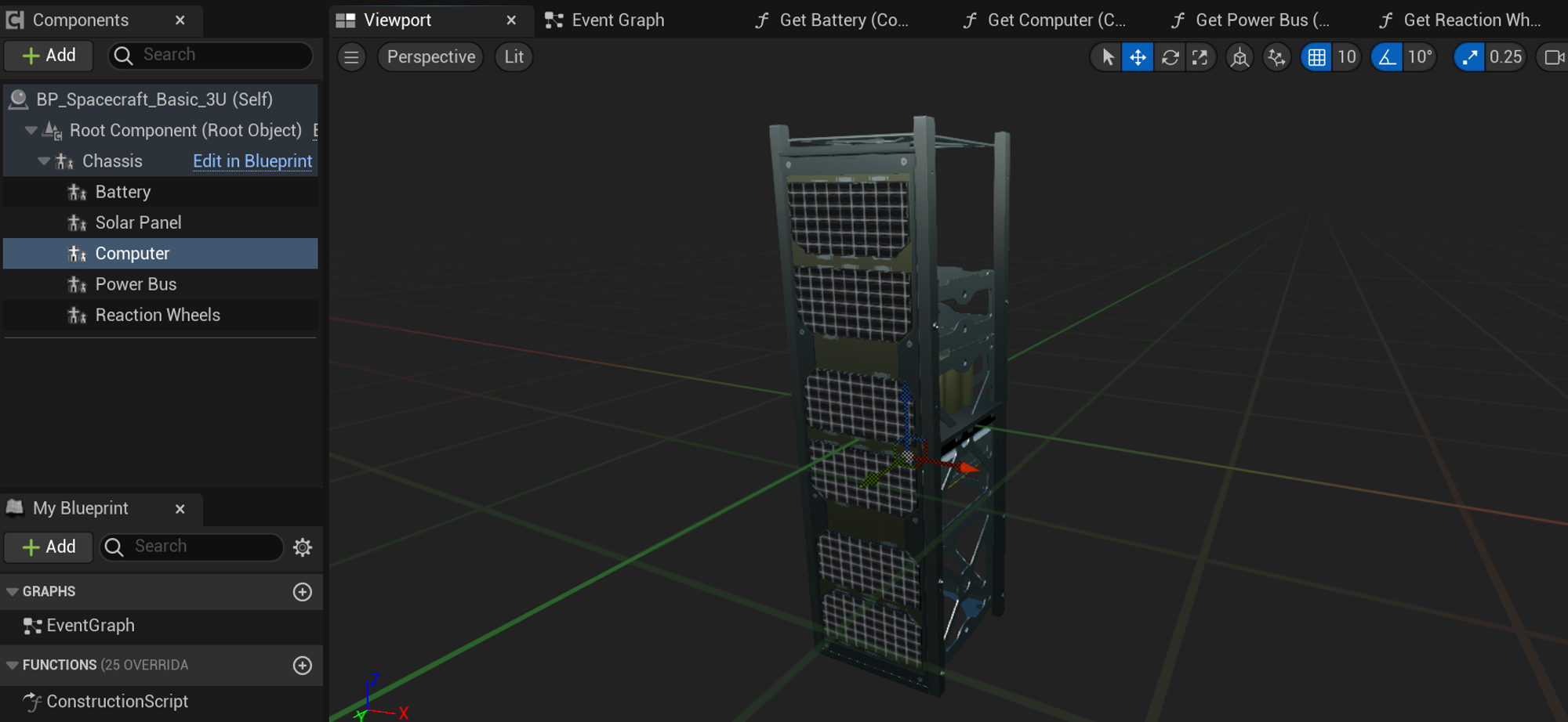
Start by configuring a level with a spacecraft spawned in orbit. The spacecraft must have the following components for this chain to work:
- Reaction Wheels
- Computer
The spacecraft can have any other number of components and instead of using reaction wheels, an external force torque module could be implemented as the effector instead. Additionally, the payload and data system that is usually used for these simulations are not shown in this guide. Data system examples will not be explained in this document.
Adding the Navigator
After spawning the spacecraft in the level blueprint, flight software can be added to the spacecraft. This is usually done in a blueprint function but can be done directly on the Event Graph. The first step is to add the Navigator component. This is required for all flight software chains, and the ground-pointing chain is no exception. The Navigator produces the estimated position and rotation of the spacecraft, with some noise values applied. It is a source of truth and does not simulate the data from a sensor. This component needs to be added to the Computer on the spacecraft, which can be done by first fetching the computer and constructing the Navigator.
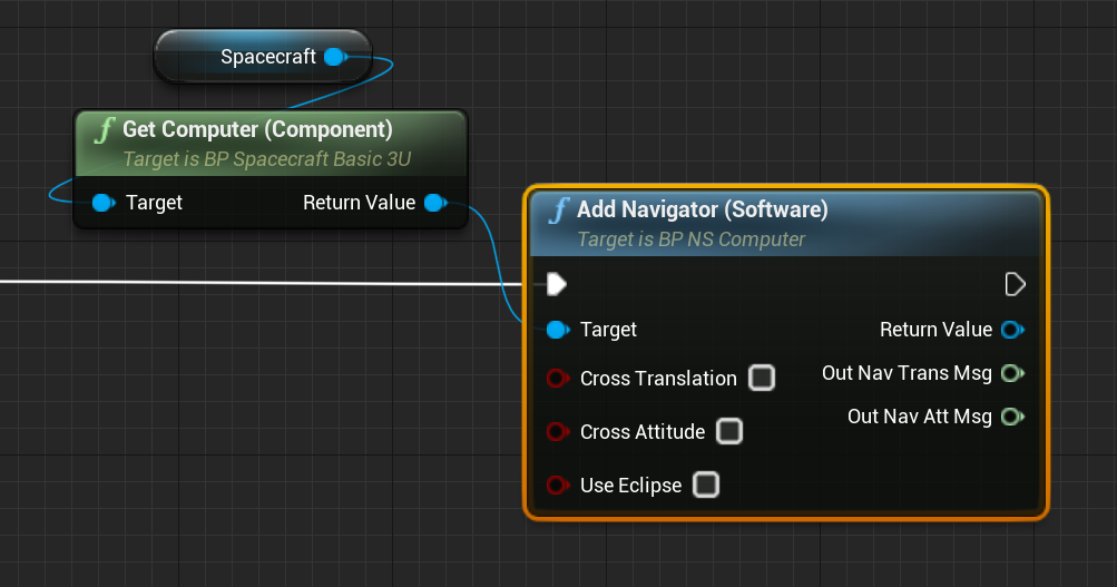
The Navigator takes three input flags, which define how the errors are added to the module:
- Cross Translation: A flag that defines a position error depending on its velocity
- Cross Attitude: A flag that defines an attitude error depending on its attitude rate
- Use Eclipse: A flag that defines whether the sun pointing vector on the navigation attitude message depends on whether the spacecraft is in an eclipse. This flag is only useful for the sun-safe pointing chain.
Adding the Ephemeris Conversion Software
The next software will convert a planet’s ephemeris message, which defines the coordinates in the inertial frame, of the targeted celestial body. This is the Ephemeris Conversion Software and allows for any celestial body, including the Earth, to be targeted with the flight software. The Universe can be used to fetch planet data and the conversion software will create a converted message. In this example, the input message is hidden with the option of selecting the targeted body.
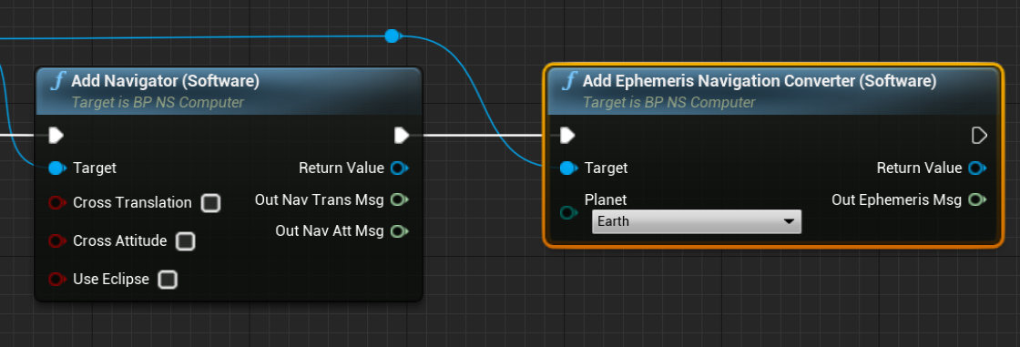
Note
If adding the component manually using the construct from class option, the input planet vector will be exposed and this can be retrieved from the Universe’s Get Universe Planet method.
Adding the Ground Pointing Software
The next software to add is the Ground Pointing Software, which will define both the guidance error and reference frame between a particular alignment vector and the ground station location. This module requires four input messages to define the target frame of the pointing vector. The first two vectors come from the navigator and define the current orientation and translational position of the spacecraft in question. The third input message is the ground state message, which contains the positional and rotational data relative to the body the ground station is located. Given the planet frame \(P\), then the data within the Ground States Message contains the position \(\space^N_P R_L\), which defines the position in the local space relative to the planet in the inertial frame \(N\). However, because the ground station message is relative to the ephemeris of the celestial body the station is located on, the fourth message requires the planet’s ephemeris message to add the position to the pointing module.
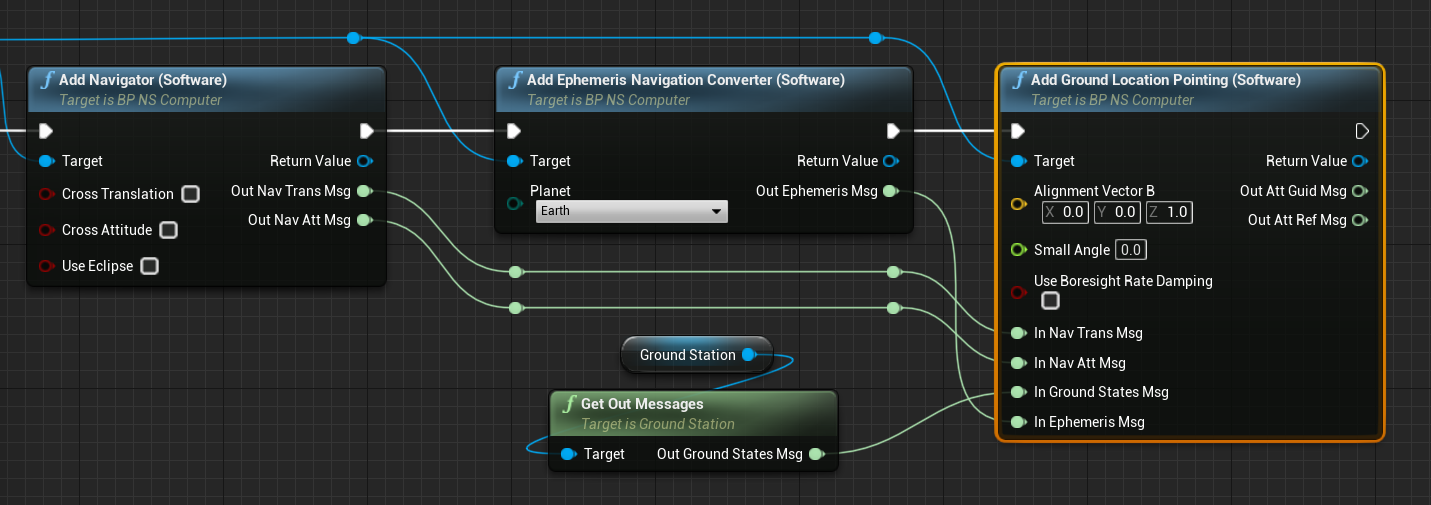
The software also takes some additional input variables that can configure the software to act under different circumstances:
- Alignment Vector: A vector represented in the body \(B\) frame that the spacecraft will align its orientation with.
- Small Angle: The smallest possible angle between the alignment vector and the ground vector that can be reached before the software stops producing guidance messages.
- Use Boresight Rate Damping: A flag to use rate damping about the sensor boresight.
Adding the MRP Feedback Software
A standard software module that is used for all pointing chains is the MRP Feedback Software. This software module takes in a desired guidance direction and compares the direction with the current orientation. It then uses a PID controller to create a torque message that will define how much torque is given to the effectors (such as a reaction wheel or external force module) to start orienting the spacecraft in the desired vector. The guidance message is a requirement as the input for the module, however, the reaction wheel messages (speed, availability and config) are optional and can be used when a reaction wheel exists. These messages provide information to the controller on the configuration and speed of each reaction wheel and can optimize the controller for specific wheels.
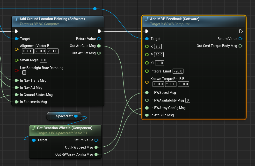
The MRP controller is configurable and the PID constants can be adjusted. These parameters are dependent on the state of the system and the friction models on the reaction wheels. The default constants are suggestive and work in a majority of use cases.
- K: The proportionality-gain constant (P) to the MRP errors.
- P: The rate-error constant (D) for the feedback gain.
- Ki: The integration feedback error constant (I) on rate error.
- Integral Limit: The integration limiting torque to avoid wind-up issues.
- Known Torque Point B_B: The defined additional external torque, defined in body frame coordinates, that is applied to the controller.
Adding the Reaction Wheel Motor Torque Software
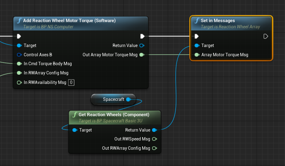
The MRP controller will return an expected torque for some effector to apply on the spacecraft in the body frame. If a reaction wheel module is used, then this torque needs to be converted to a reaction wheel command, that can be sent to the reaction wheel array on the spacecraft. This is the Reaction Wheel Motor Torque Software and it takes in the state of the reaction wheels (as a configuration message) and the required torque command and produces an array motor torque message, containing a list of torques that are to be applied to a reaction wheel. By default, if no availability message is defined, the module will assume all reaction wheels that are configured are available and operable in the system.
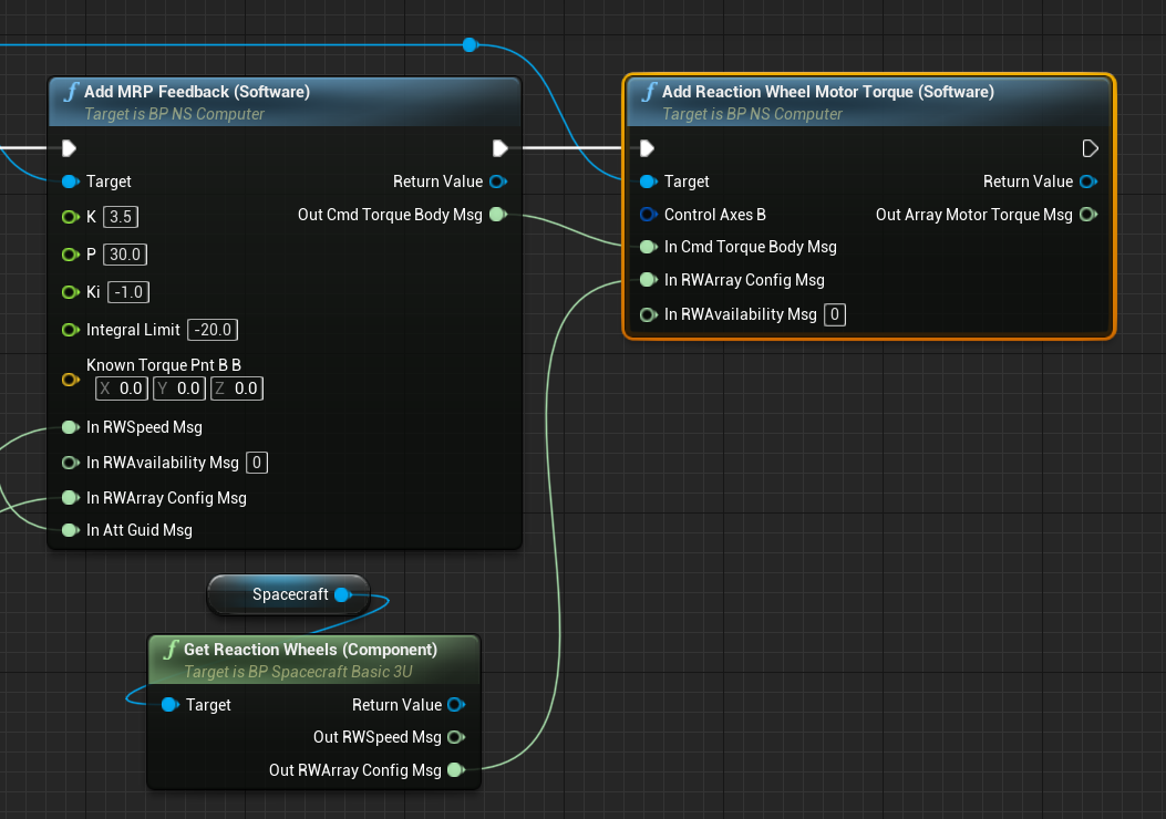
The reaction wheel motor torque software has one additional parameter, defined as the control axes. This parameter defaults to the identity matrix but can be configured to define a non-symmetrical axis of control, in the case that a reaction wheel or software produces the torques in a rotation that is not equivalent to the reaction wheel direction vectors.
Connecting the Reaction Wheel Message
The reaction wheel motor torque software produces an array message that the reaction wheel uses to control the torques of each wheel. The final task of the flight software chain is to connect the message to the reaction wheel. This can be done using the Set In Messages method, which is the standard syntax for updating the input messages of a component.
These are all the required software modules for the ground-pointing chain to be implemented on a spacecraft. Additional software modules can be added for specific use cases, such as a power voltage conversion. The ground state message can also be published from the ground station via the data system for a full in-the-loop simulation.