Editor: Reaction Wheel Momentum dumping
Description
This guide showcases how to use magnetometers to sense the local magnetic field to aid attitude determination to guide the pointing of a satellite while simultaneously using magnetic torque bars to desaturate reaction wheels.
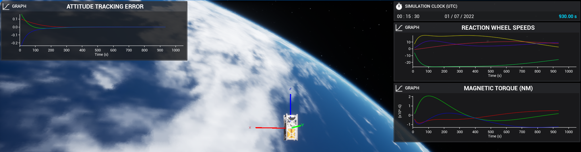
The example scenario can be found at the Dynamics/Demo_MomentumManagement level. It uses a combination of reaction wheels and magnetic torque bars to orient the spacecraft into an inertial-hold-pointing mode while simultaneously desaturating the reaction wheels i.e. driving the speed of all the reaction wheels to zero.
Creating the Spacecraft
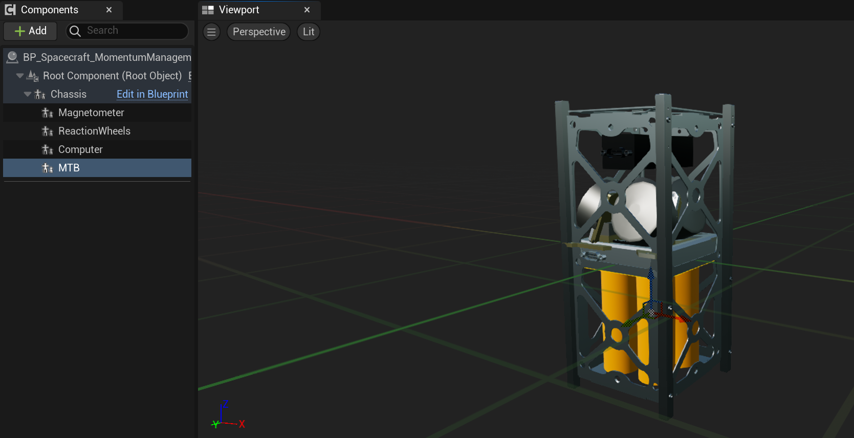
Start by configuring a level with a spacecraft spawned in orbit. The spacecraft must have the following components for this example:
- Reaction Wheels (
BP_ReactionWheels_MM) - Computer (
BP_NS_Computer) - Magnetometer (
BP_NS_MagnetometerSensor) - Magnetic Torque Bar Array (MTB) (
BP_Spacecraft_MomentumManagement)
The spacecraft shown below is used for this guide. It is provided within the example spacecraft blueprints (BP_Spacecraft_MomentumManagement_2U).
Adding the Attitude Control Flight Software
Next, after spawning the spacecraft in the level blueprint, flight software can be added to the spacecraft. The flight software required for this example will be the:
NavigatorInertial Hold SoftwareAttitude Tracking Error SoftwareMRP Feedback Software
These modules are added identically to those described in the corresponding sections within the Editor: Inertial Hold Pointing Chain tutorial. They provide the basic pointing mode for the spacecraft in this example. However, the rest of this example will differ from the simple inertial hold pointing chain in that it will use magnetic torque bars and momentum management flight software modules, in addition to reaction wheels, to actuate the rotation of the spacecraft.
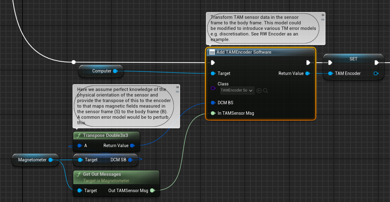
Adding the TAM Encoder
The Three Axis Magnetometer (TAM) Encoder is a flight software module that transforms TAM sensor data from the sensor frame to the body frame. This module can be added via the TAM Encoder Software component which takes the TAM sensor output data and a direction cosine matrix (DCM) that defines the orientation of the sensor in its sensor frame to that of the body frame. This input DCM is configurable by the user.
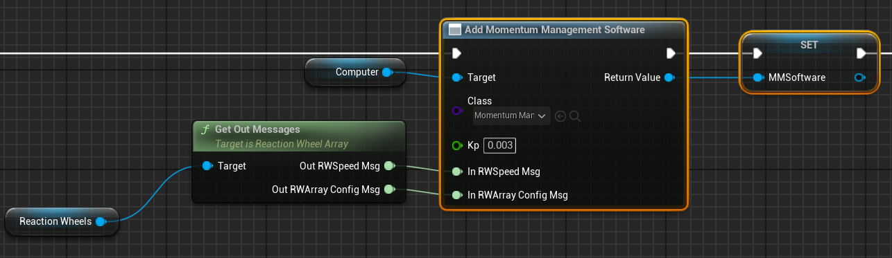
Adding the Momentum Management Software
The Momentum Management Software module calculates the body frame torque required to dump momentum stored in a reaction wheel array based on an input proportionality gain (\(k_{p}\)). The module takes the reaction wheel configuration and speed messages as input to calculate the required torque. The torques are used as input into further flight software modules that eventually provide input commands for magnetic torque bars.
Adding the Torque to Dipole Software
The Torque to Dipole Software module takes a torque command and converts it to required magnetic dipole commands based on the local magnetic field sensed by the magnetometer.
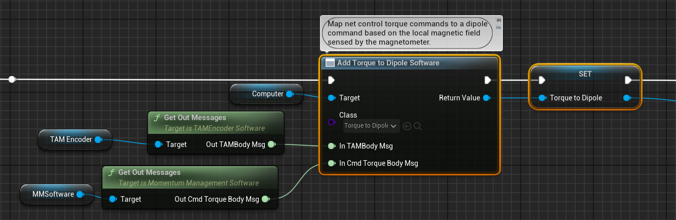
The commanded torque is an input parameter into the Torque Dipole module. In this example, it originates from the output of the Momentum Management Software module. The module also takes the sensed magnetic field from the TAM Encoder flight software module as input to aid the calculation of the dipole commands.
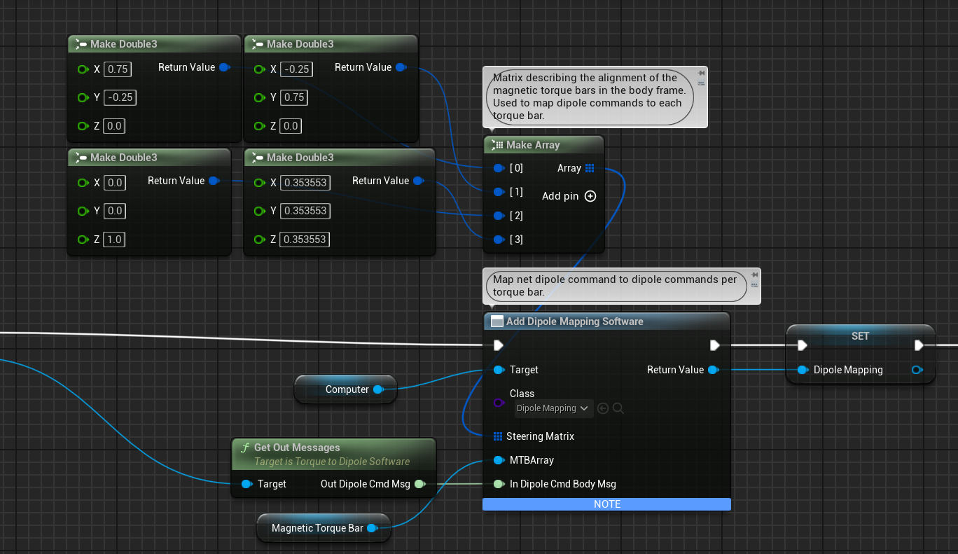
Adding the Dipole Mapping Software
The Dipole Mapping Software module takes input dipole commands and maps them to individual magnetic torque bars within a magnetic torque bar array. As such, the module takes the Torque to Dipole command as input in addition to an array of vectors that define the orientation of the magnetic torque bars in the body frame.
Adding the MTBFeedforward Software
The MTBFeedforward Software module is a flight software module that takes the torque commanded of a magnetic torque bar array to desaturate reaction wheels and adds it to the torque command produced by the MRP Feedback control software to produce a torque command for the reaction wheels that will achieve stable pointing while also allowing the reaction wheels to be stabilised based on the feedforward controller.

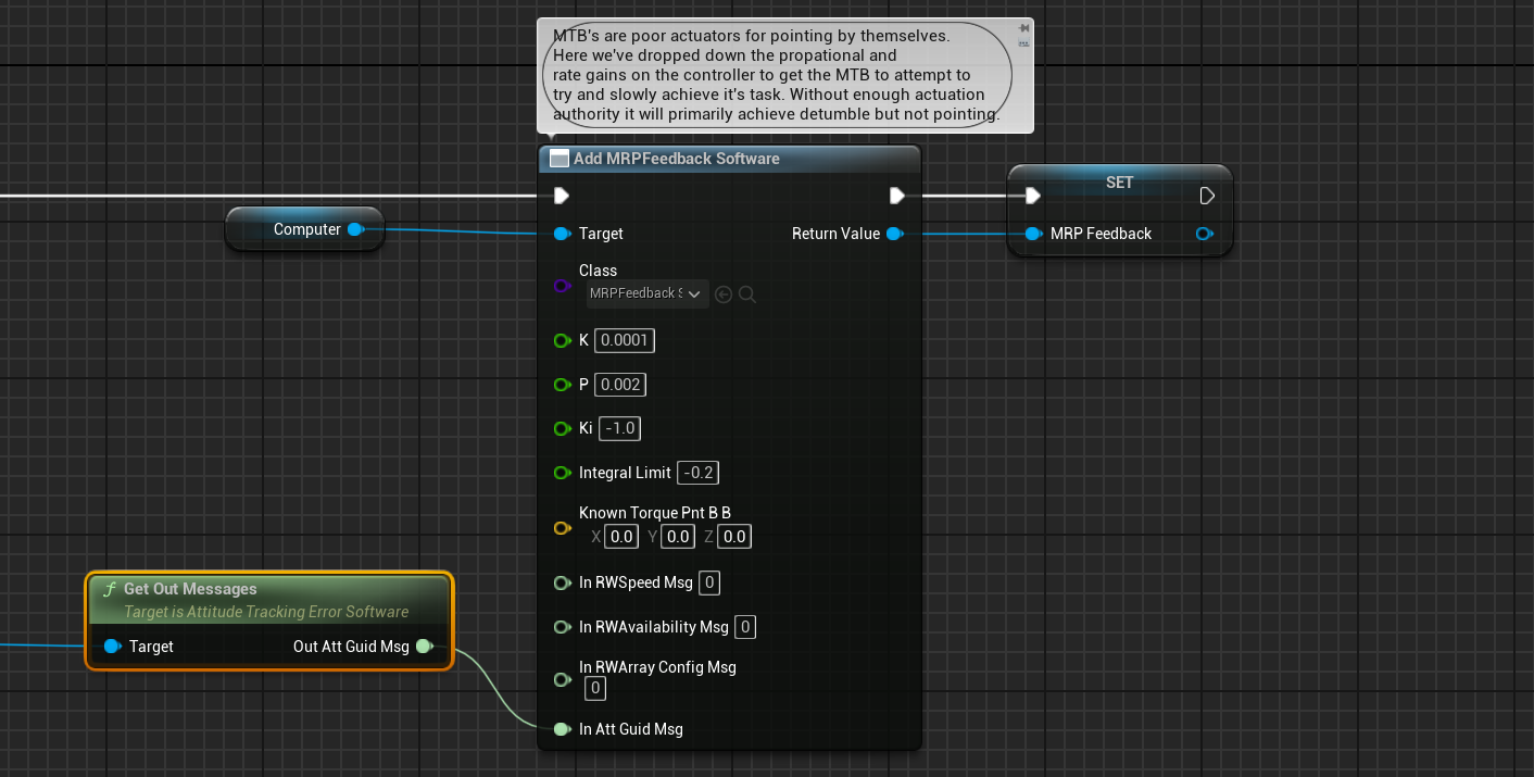
Additional MRP Feedback documentation can be found in the previous guide, with the specifics of this implementation of MRP Feedback software shown below.
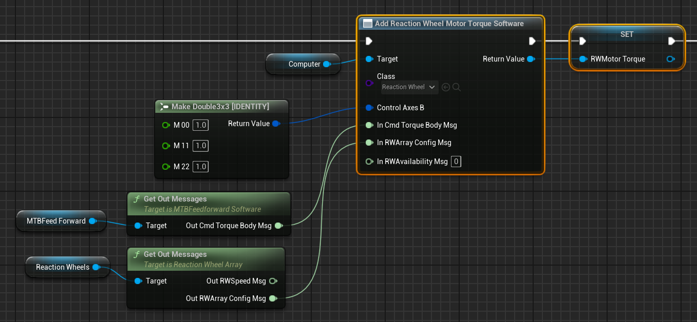
Adding the Reaction Wheel Motor Torque Software
The reaction wheel motor torque message is described within the inertial hold example. However, instead of getting the input commanded torque from the MRP PID controller, in this example, it gets the command from the Magnetic Torque Bar Feedforward controller module as is shown below.
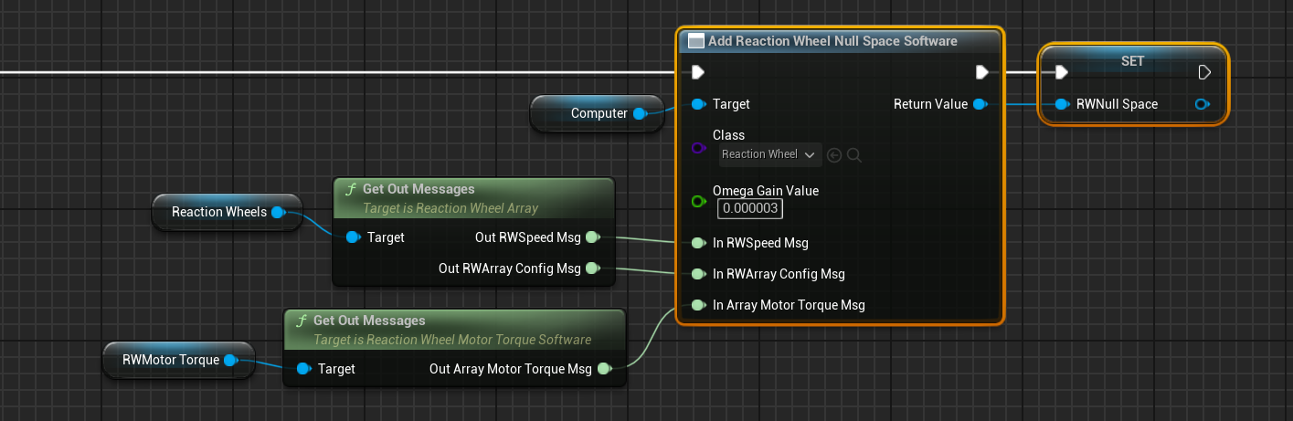
Adding the Reaction Wheel Null Space Software
The Reaction Wheel Null Space Software drives the reaction wheel speeds to a desired value based on the input reaction wheel motor torque. It results in motor torque commands for every reaction wheel in the reaction wheel array that will desaturate the reaction wheels i.e. driving their speeds to a desired value without affecting the stability of the attitude control setup. By default, the target reaction wheel speeds will be zero.
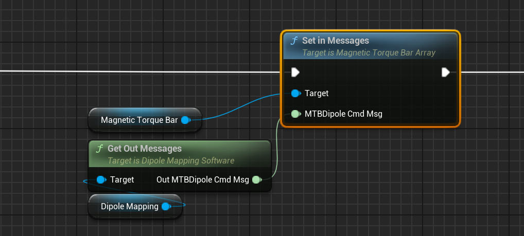
Adding the MTBDipole Command Message
The MTB Dipole command should be added to the MTB array by linking its input message to the output message of the Dipole Mapping software.
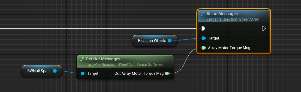
Adding the Reaction Wheel Motor Torque Command Message
The reaction wheel motor torque for every reaction wheel in the reaction wheel array should be linked to the output message of the reaction wheel null space module.