Power Network: Controlling Power Nodes
Adjusting the Load
For this tutorial, when the camera takes an image, the camera should take some power from the battery. In a previous document, the power load was configured in the power network to be the load that uses battery power. This can be done by adjusting the resistance of the load. Using the formula:
where \(P\) is the power, \(V\) is the voltage and \(R\) is the resistance of the node, given that the voltage is constant, the lower the resistance, the more power is used by the component. As such, changing the resistance of the load to something small (but non-zero), will draw power from the network and drain the battery. Once the image is taken, the resistance of the load can be changed to another value.
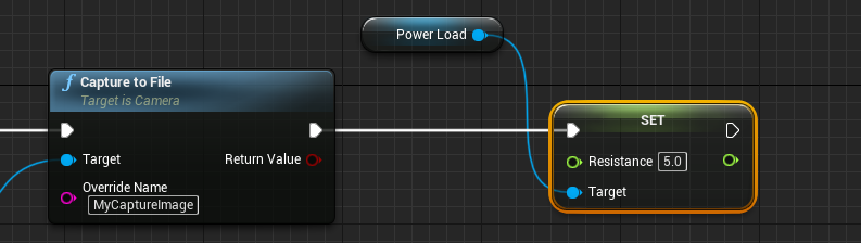
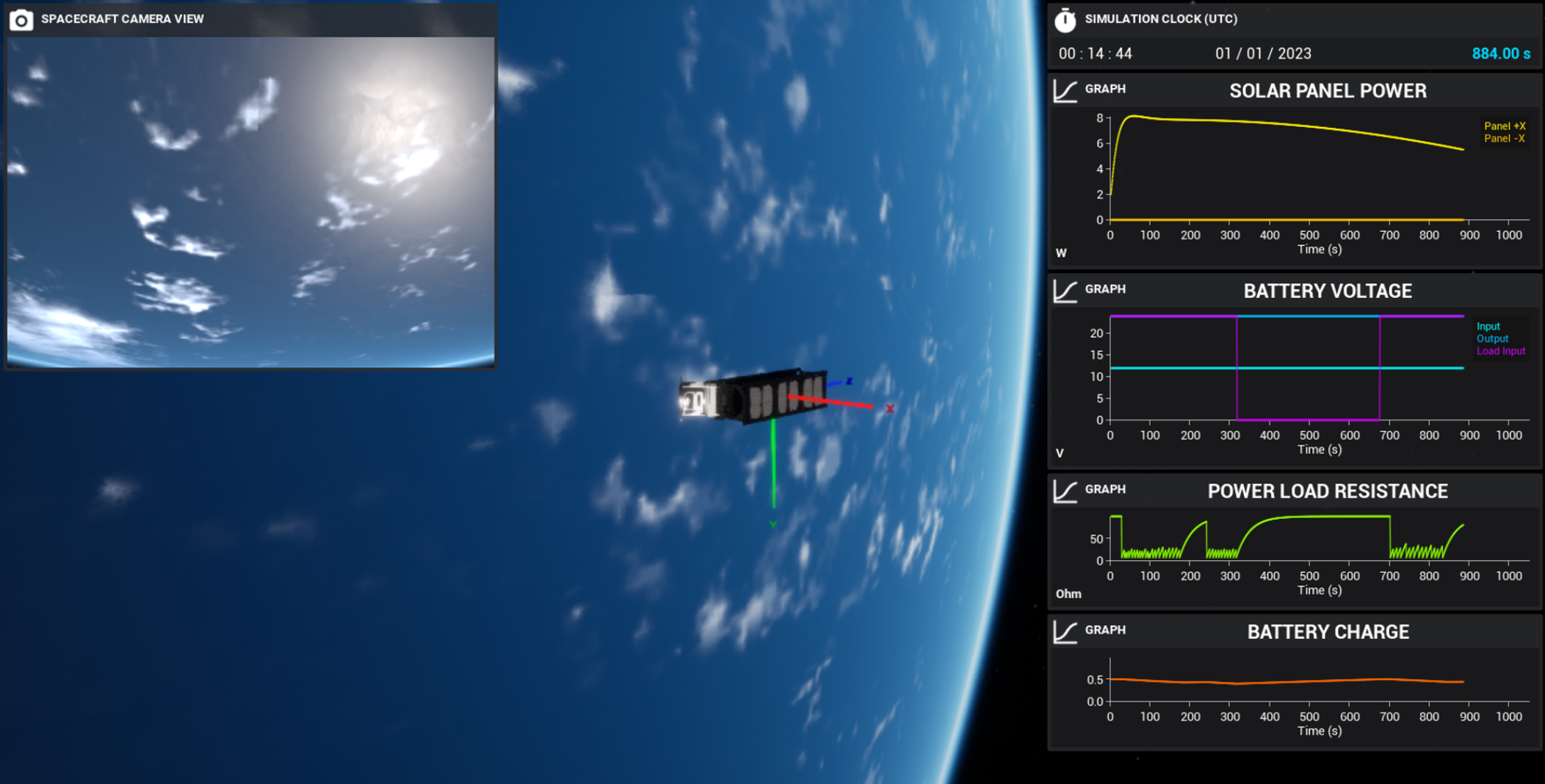
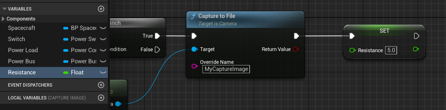
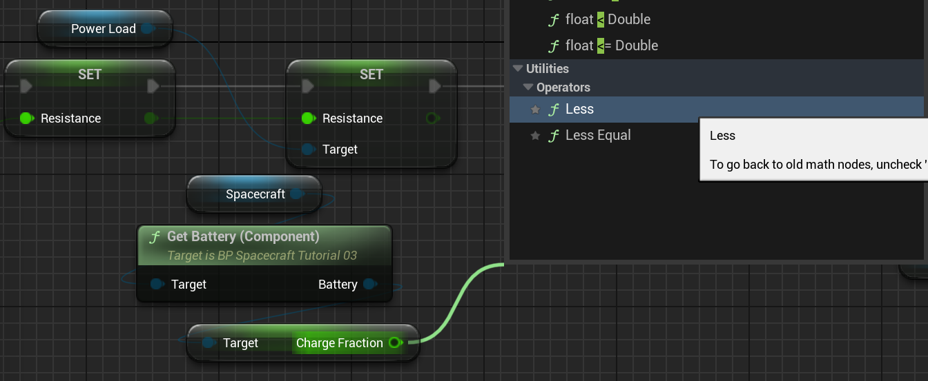
When the simulation is played and the image is taken, the battery starts to drain. However, it does not stop and will continue to drain until no charge is left in the battery. This is not ideal for this simulation as it would assume that the camera is constantly drawing power. A better approach to this is to use a linear interpolation between some value and 100 and update that value when the camera is used. By having a high resistance, very little current will be drawn from the camera load. The resistance can then be updated to the interpolated value. Start by creating a new float variable, named Resistance, and setting the default to 100 ohms. When the camera takes the image, that variable should be set to 5 ohms (or some appropriate number).
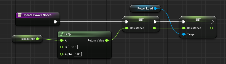
Then, on the Tick event, a new function called Update Power Nodes can be created. Within this function, the resistance should be updated so that it uses a linear interpolation between the current value and 100. Typically, functions like this should occur before updating the user interface, as the UI should be the last step in each event. The alpha value defines the interpolation value, which can be hard coded. From there, the resistance of the load itself can be set to the value from this variable.
Toggling a Switch
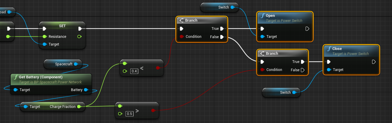
The switch in this circuit allows current to flow from the battery to the load. The switch starts closed, where the current can flow correctly. If the switch is opened, then the current is prevented from flowing and no power will enter the camera power load. For this model, the switch will be opened, preventing power flow, when the battery charge drops below 40% and the switch will be closed again when the battery charge reaches 50%. This can be done with an if statement. In the Unreal Engine, these are branch nodes. A branch node takes in a condition and returns a true and false execution pin, based on whether that condition is met. The code we want to execute is:
if (charge < 40%) {
	switch.Open()
}
else if (charge > 50%) {
	switch.Close()
}
Conditional values with floats can also be replicated in Unreal. By using the < and > operators, a condition can be constructed and passed into the branch condition. The Less method is a new method available in Unreal 5 for easy math operations.
As such, the entire functionality of the switch system can be designed with the blueprint nodes shown below. This includes opening and closing the switch when the particular conditions are met.
Capture Logic
Returning to the Capture Image function, some logic needs to be implemented so that the camera can only take a photo if the input voltage to the power load is greater than 0. If the load is not receiving any power, then the image cannot be taken. This can also be done with a branching node and by reading the Voltage variable on the power component.
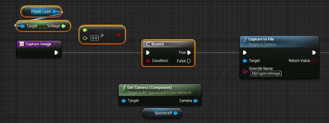
In this case, when the switch is opened and no voltage is being received by the camera, the camera will be unable to capture a new image to a file and render the image.
Graphing the Load Voltage
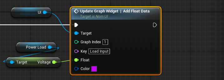
The voltage of the power load can also be added to the battery voltage graph. A third data point can be added to the graph of index 1 (the second graph) which will demonstrate the voltage passed into the load. This is to show when the switch opens and the voltage changes to zero.
Capturing Images
When the simulation starts, continuously pressing the capture button will allow the battery to decrease its storage to under 40%. When this happens, images can no longer be captured until the solar panels charge the battery back to their original level.