Power Network: Configuring Cameras
Adding a Camera
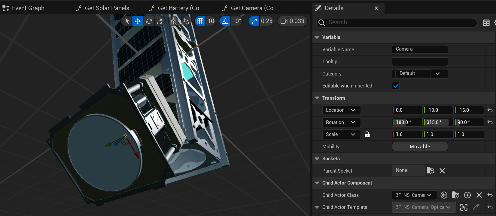
On the spacecraft blueprint, a new component can be added to the spacecraft. This is the camera and will be able to take photos of the world around. There are two types of cameras exposed in Nominal Editor; an optical camera and an infrared camera. The infrared camera can take photos of simulated infrared radiation from the temperature of components that are visualized. This will not be covered in this tutorial. The BP_NS_Camera_Optical will be used for the camera component.
Note
For this tutorial, position and rotate the camera in any direction. The white circle on the mesh indicates the location and which the camera will be taking photos (the blue Z-axis line when selected). This design above is a little unrealistic but will be able to demonstrate imaging the Earth and blocking a portion of the solar panel area.
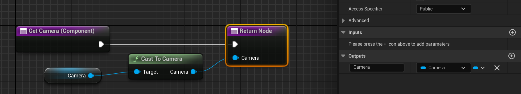
Ensure that a suitable function called Get Camera (Component) is also created on the spacecraft and returns the instance of the Optical Camera class. The Cast To Camera function will take in a child actor and is able to cast to an optical camera type.
Configuring the Camera
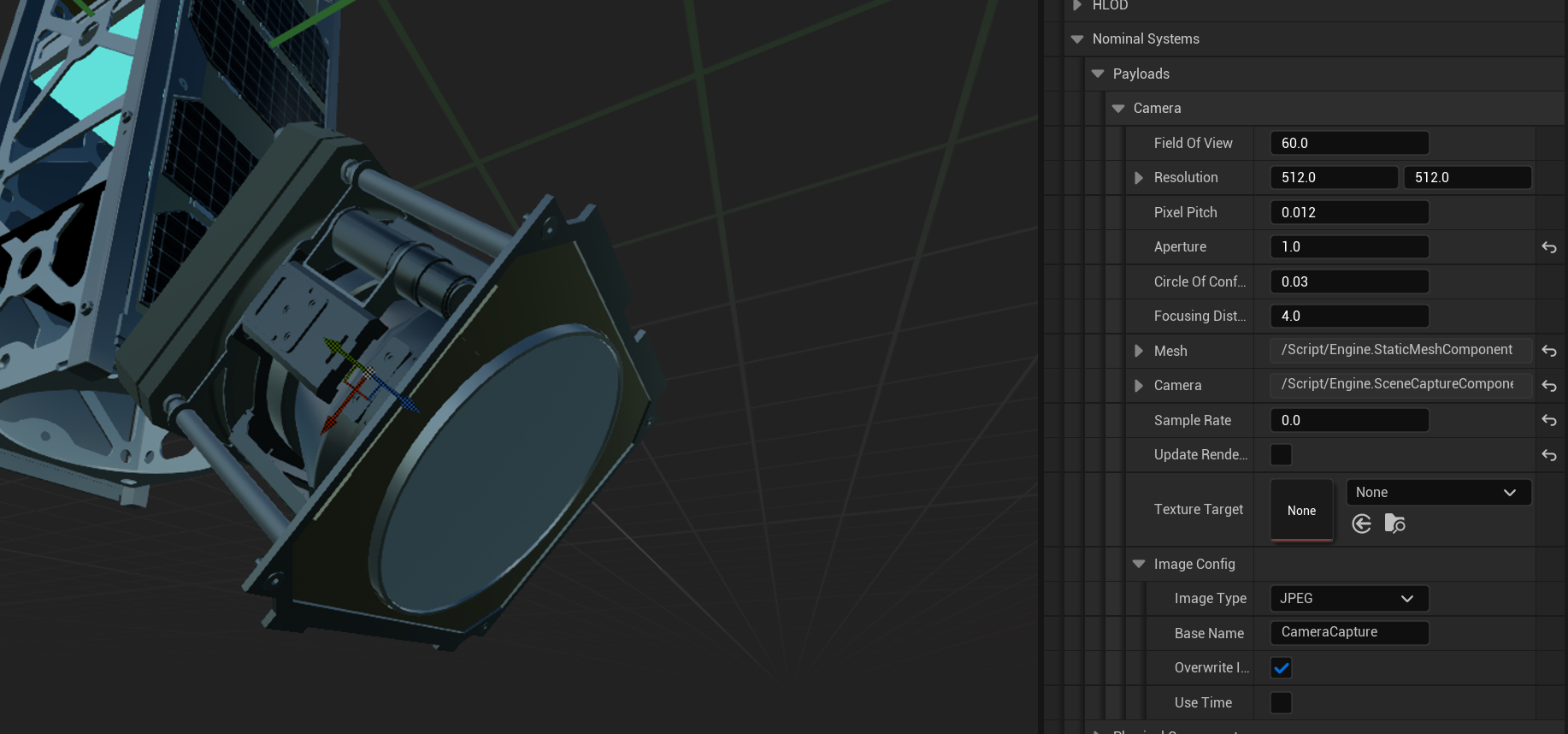
The camera has several configurable parameters which will be adjusted for this tutorial:
- Field of View: This is the angle in degrees that the camera can see. The larger the field of view, the greater the area that can be imaged.
- Sample Rate: This is the default time in seconds between captures of the camera. For this tutorial, we will use manual capturing rather than automatic.
- Resolution: This is the size in pixels that the camera will image. This is unaffected by the field of view and will always consist of images of this size.
- Update Render Each Frame: This flag determines whether the camera render target will be updated all the time. By disabling this flag, the image will only be updated when the capture function is called.
- Texture Target: The texture target from the camera. If left blank, a new default texture will be created for the image.
- Image Config: This provides some additional configuration for the camera image that is saved.
- Image Type: The type of image that is exported including JPG, PNG and EXR formats.
- Base Name: The name of the saved image to export.
- Overwrite Image: A flag whether to overwrite an image saved if it has the same name
- Use Time: A flag whether to use the simulation timestamp as part of the image save name.
For this tutorial, the following values are used for the camera configuration:
Adding a Camera Widget
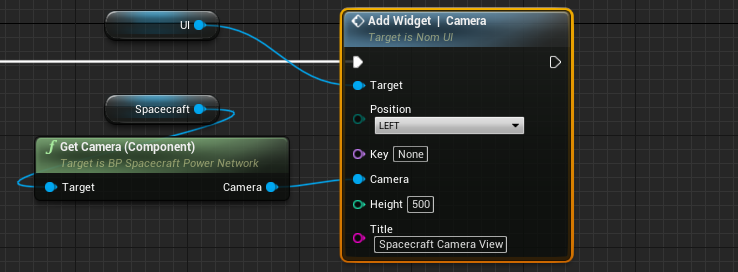
To view the feed from the camera, a camera widget can be displayed as a user interface element. This widget will display the current view from the camera once an image is saved. This can be added to the Nom UI component using the Add Widget | Camera function. This widget also has several parameters exposed:
- Key: The name of the camera view for use with multiple camera widgets. This is useful for toggling the widgets by the key name.
- Camera: The connected camera that the camera view will be displayed from on the screen.
- Height: The height in Unreal coordinates of the UI widget.
- Title: The name of the camera view that will be used on the title of the widget.
In most cases, the default values are sufficient.
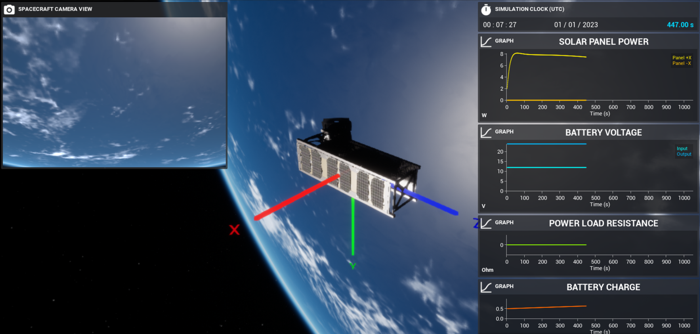
Displaying the Camera Feed
When the simulation starts, the camera view will appear empty and a black image will be shown. This is because the toggle for Update Render Each Frame was disabled. With this, only when an image is taken will the image on the screen be updated. To test that the camera is working correctly, the toggle can be turned back on and when the simulation starts, a live feed from the camera will be shown on the UI element.
Note
Ensure to disable this toggle (found in the camera settings on the child actor) for the remainder of the tutorial.