Power Network: Configuring a Power Bus
Designing the Network
The power bus allows for a network of power nodes on an electrical power system (EPS) to be designed and connected. The power bus provides the backbone for a power network and can allow components to draw and provide power to and from the central battery unit. A power bus allows for simple circuitry designs, with both parallel and series power networks. For more information on how the power bus functions, visit the appropriate Technical Manual page for the Power Bus component. For this tutorial, the five power components (2 solar panels, battery, switch and load) will be connected in the following configuration:
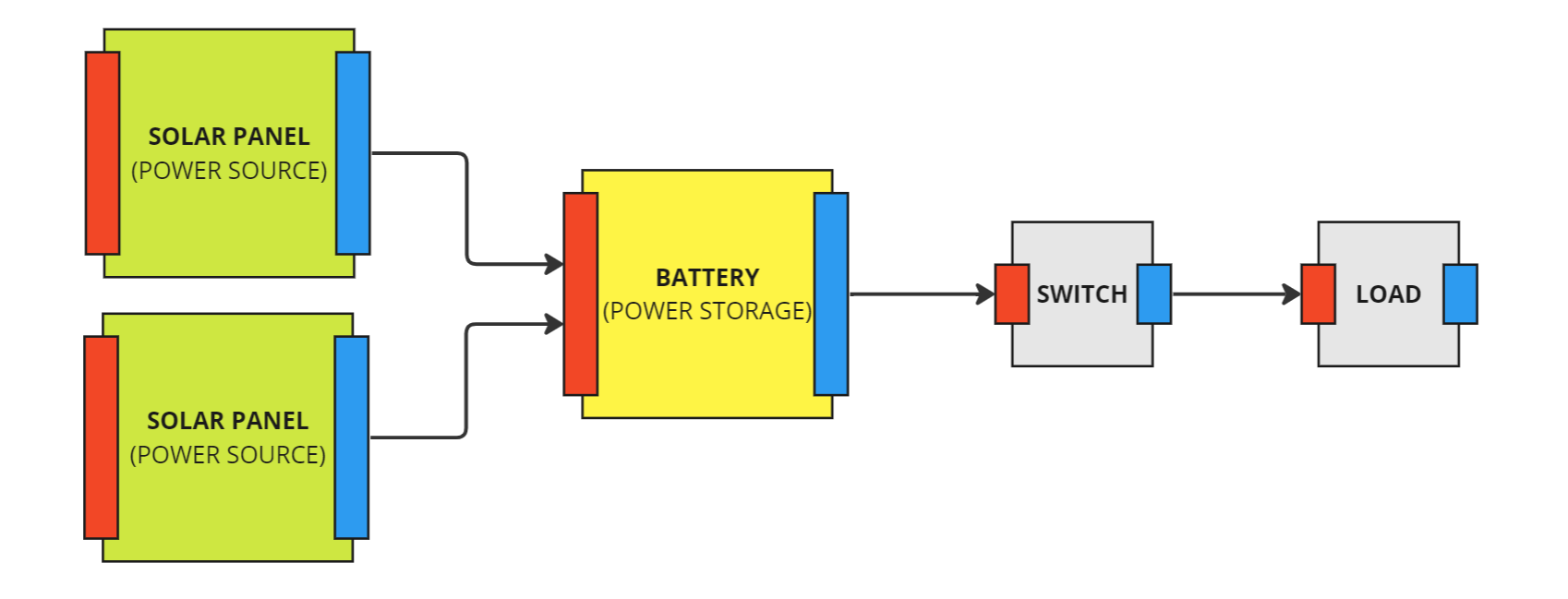
Here, the two solar panels provide power to the battery in parallel, each providing 12V of power to the battery node. The battery will be providing an additional 12V of power to the nodes on the right-hand side of the battery. These two components, the switch and the power load for the camera, will receive 24V of power when the circuit is closed and are configured in a series circuit. This is a simple circuit design and can be implemented with the power bus.
Note
For the power bus, the connection from the end of the component lines back to the positive end of the solar panels can be imagined and is not required to be connected to the system. This is to ensure the EPS design can be simple and easy to implement.
Adding the Power Bus
The Power Bus component must be spawned and added to the spacecraft. This can be done in the same way as the other power components and does not require any changes to the exposed variables.

Connecting the Nodes
The power bus contains several connection functions for connecting the different power nodes. These nodes are defined by what kind of components are required to be connected. There are three types of power components:
- Source: A power source that can provide a charge to the battery, such as solar panels.
- Storage: A battery that can contain the power in the system and both distribute it and charge from power sources.
- Node: A power node that can draw current and voltage from the power network and includes switches and power loads.
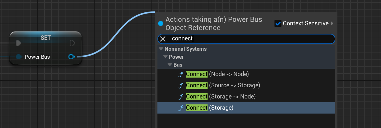
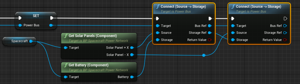
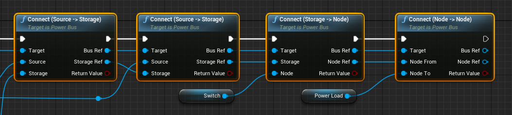
Each of the components can be attached in this way. The two solar panels need to be connected to the battery. They are done in parallel so the Connect (Source -> Storage) function needs to be called twice. This will connect each solar panel to the battery.
Note
The ref values at the output of the function provide an easier way to call the functions again with the same value. The Bus Ref value provides the same reference to the power bus as the one input, making it cleaner for the nodes to connect. The Storage Ref value is a reference to the same battery that is parsed into the first node.
The next component to connect is the switch. The switch can be connected using the Connect (Storage -> Node) function and uses the storage ref as the input and the switch as the second input as the node. This will connect the battery to the node in a series circuit. Additionally, the final component, the power load, can be added to the switch node using the Connect (Node -> Node) function on the power bus. The full network will look like the following:
Testing the Network
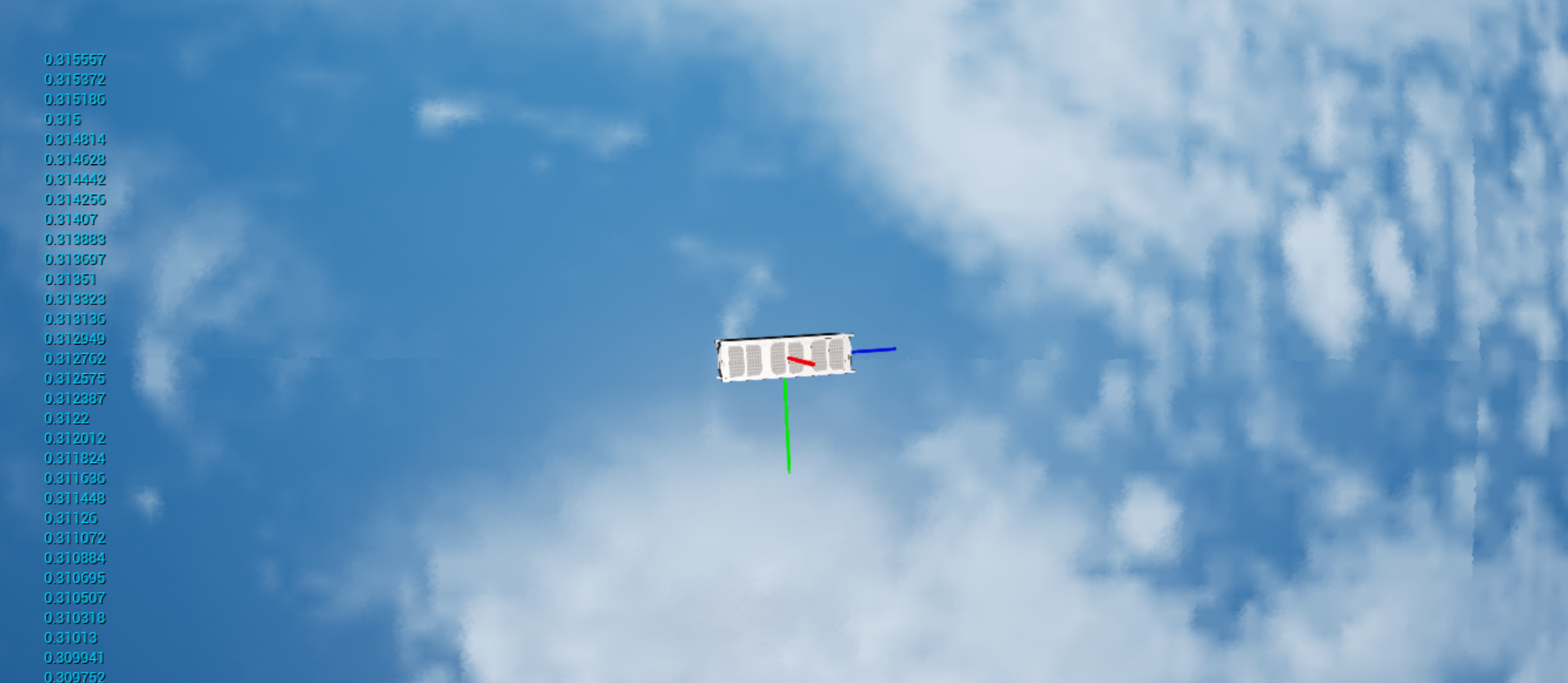
Although the switch and load should be doing nothing to the power network, the solar panels should be providing power to the battery. This can be tested and checked by printing out the charge of the battery to the screen and running the simulation.
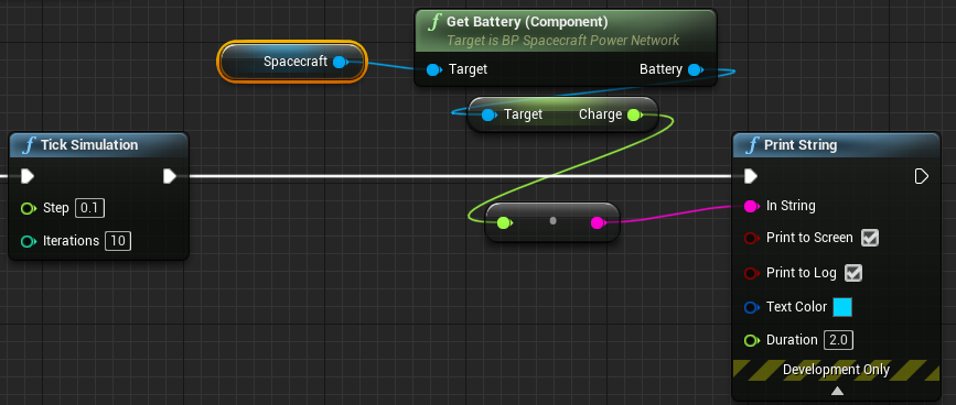
The battery charge of the spacecraft should appear to increase over time by looking at the text printed in blue on the left-hand side.