Power Network: Configuring Power Nodes
Configuring Solar Panels
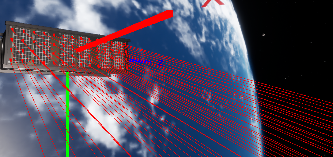
A solar panel has several properties that can be configured within a simulation. The properties that can be adjusted include the area, voltage, efficiency and the raycasting toggle. Raycasting is a graphical algorithm that can determine the distance to objects along a fixed path in a defined space. The Unreal Engine makes use of raycasting for its graphics systems but it can be utilized for more precise calculations. On the solar panels, a feature has been implemented that, when enabled, allows for more accurate shadow values to be calculated. By default, the solar panel is only affected by shadows from celestial objects when in eclipse from the sun. If a complex shape is formed where an object on the spacecraft itself is blocking a portion of the sunlight, by default it will not change the power produced by the solar panel. A solution is to enable raytracing by selecting the Enable Self Shadowing toggle on the two solar panels on the spacecraft.

Turning on the Debug flag under the Nominal Systems/Physical Object category will display the raycasts on the screen and show how the raycasts are created on the solar panel. For the actual simulation, this debug option will be turned off.
Configuring the Battery
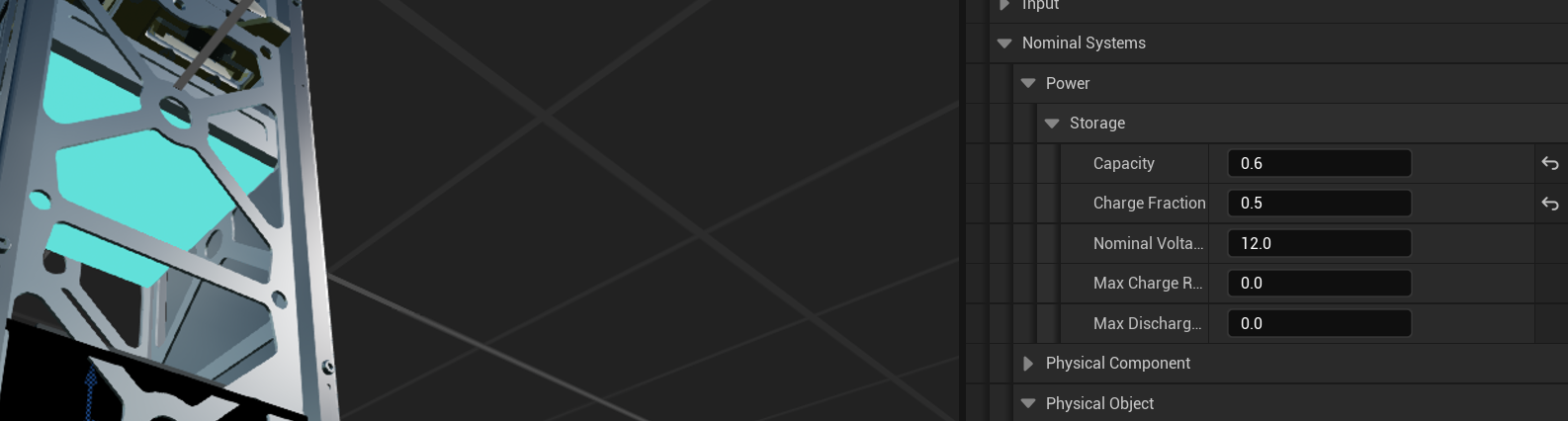
The battery, or power storage node provides the storage of power that can be dispersed into the rest of the system. A battery can gain and lose power through the power system by connecting power nodes to it via the power bus, which will be covered in the next document. Several values can be tweaked on the battery:
- Capacity: The total capacity in amp-hours of the battery.
- Charge Fraction: The current fraction (between 0 and 1) of power that is in the battery right now.
- Nominal Voltage: The standard voltage produced by the battery when in a nominal state.
Note
The battery model is a simple battery and the voltage produced by the battery does not change with the current charge state of the battery. The voltage will change to 0 when the charge fraction of the battery reaches 0.
- Max Charge Rate: The maximum rate the battery can be charged (if non-zero) in the units of amps.
- Max Discharge Rate: The maximum rate the battery can discharge power (if non-zero) in the units of amps.
For this tutorial, the following values will be used for the battery component that is added.
Adding a Switch
The next power node to add to the system is a power switch component. The power switch will allow for current to flow in and out of a particular circuit. If the switch is open, all power nodes on that circuit (both before and after the switch) will be shut off and no power will be drawn by those nodes. The power switch does not have a mesh and is typically added in the level blueprint instead. The location and rotation of the power components do not matter in this case. The resistance should be set to 0.0 as default, which will skip the component.
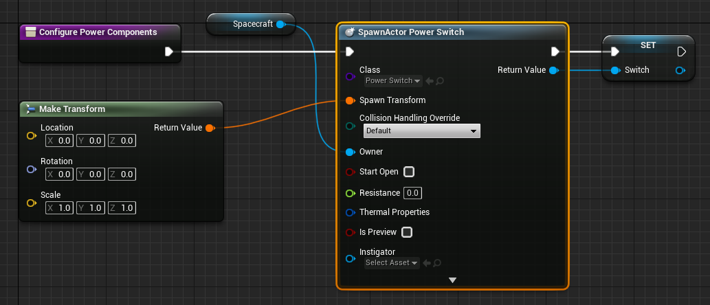
Make sure to change the resistance to 0.0 ohms, as the switch should not be using any current. Any power component with no resistance will assume it is not drawing power from the circuit.
Adding a Power Load
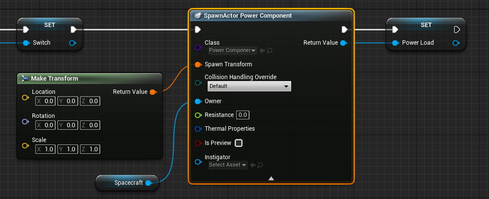
The last power node to be added is a power load component. This will be a component that will be drawing power as the camera takes images. A power load can be created by spawning a Power Component, which is a generic component that can have its resistance changed over time from user events, such as taking a photo from a camera. Again, the power component should also have no resistance to start with. The resistance should be set to 0.0 as default, which will skip the component.
Warning
Remember to always add the spacecraft to the owner field when adding components to a spacecraft. This is required otherwise the component will exist in the simulation without a parent.