Editor: Spacecraft Custom Trajectories
Description
The spacecraft has several different options for creating an initial orbit about some planetary body. However, in some cases, lookup tables can be used for positioning and orienting a spacecraft about some axis. There are several options for interpreting rotations from a lookup table, which can be defined in different coordinate frames. This guide will demonstrate how to configure a lookup table and how to initialize a spacecraft with the data in Editor. Nominal Editor provides three demo scenarios that showcase examples of these lookup tables:
Orbit/Demo_AircraftTrajectory: An example of multiple geodetic orbits with the three horizontal coordinate frames being looped overOrbit/Demo_CustomTrajectory: An example of a geodetic orbit with a pointing velocity for the orientation of the spacecraft in this frameOrbit/Demo_NonOrbitalTrajectory: An example of an inertial coordinate lookup with the object being simulated once the data is exhausted
Configuring a Table
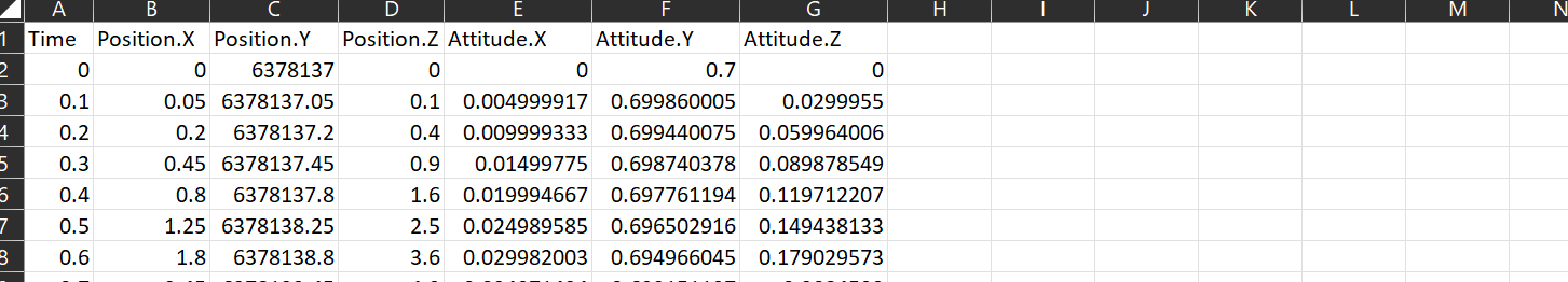
A lookup table is a simple csv file that contains a simulation time (in seconds since the start of the simulation) and a series of data associated with the position and orientation of the spacecraft at that time. There are several column types that can be used in the data for both position and rotation of the spacecraft object.
Note
The lookup table should be saved inside the Editor folder. Typically, it is saved inside the Content/Nominal/Data folder. The other data files that are used for the demo levels are found inside the Trajectories directory within that folder.
Every lookup table matches the simulation time against other parameters. As such, every single custom trajectory table must have the following column:
- Time: This is required for all lookup tables and is a timestamp in seconds since the start of the simulation. This must be the first column in the table and must be ordered in an increasing form. The time-step between data points does not need to be consistent between each row as the data will be interpolated between each timestamp.
For the position of the spacecraft, there are two options for the lookup. An inertial position or a geodetic position. An inertial position is relative to the centre of the body being orbited and is in meters based on the coordinate frame defined. A geodetic position is a coordinate around the body being orbited in latitude, longitude and altitude. Depending on the type, all three columns must be present.
Inertial Position:
Position.X: The inertial position in the X axis of the spacecraft’s centre of mass relative to the centre of the orbiting planet. This should be in meters.Position.Y: The inertial position in the Y axis of the spacecraft’s centre of mass relative to the centre of the orbiting planet. This should be in meters.Position.Z: The inertial position in the Z axis of the spacecraft’s centre of mass relative to the centre of the orbiting planet. This should be in meters.
Geodetic Position:
Latitude: The latitude value around the orbiting body of the spacecraft or aircraft measured in degrees. This should be between -90 and 90 degrees.Longitude: The longitude value around the orbiting body of the spacecraft or aircraft measured in degrees. This should be between -180 and 180 degrees.Altitude: The altitude of the spacecraft or aircraft above the surface of the orbiting body, measured in meters. This should have a value of at least 0 meters.
There are four options available for describing the rotation of the object. They include a standard satellite attitude value and three new horizontal coordinate systems (HCS). These coordinate systems point the spacecraft’s right vector towards a particular frame. For each of the HCS frames, three fields are required; pitch, roll and yaw. These are relative to the particular frame in that frame’s system.
Inertial Rotation:
Attitude.X: The spacecraft attitude value in units of Modified Rodriguez Parameters (MRP). This is a rotation system where each value is between -1 and 1 and this field is the designated value in the X axis.Attitude.Y: The spacecraft attitude value in units of Modified Rodriguez Parameters (MRP). This is a rotation system where each value is between -1 and 1 and this field is the designated value in the Y axis.Attitude.Z: The spacecraft attitude value in units of Modified Rodriguez Parameters (MRP). This is a rotation system where each value is between -1 and 1 and this field is the designated value in the Z axis.
North East Down (NED) Frame:
NED.Pitch: This is the NED frame where the right-vector is in the local North direction, the up-vector is in the down direction and the forward-vector is in the local East direction. This field describes the pitch angle clockwise about the forward axis in degrees.NED.Roll: This is the NED frame where the right-vector is in the local North direction, the up-vector is in the down direction and the forward-vector is in the local East direction. This field describes the roll angle clockwise about the right axis in degrees.NED.Yaw: This is the NED frame where the right-vector is in the local North direction, the up-vector is in the down direction and the forward-vector is in the local East direction. This field describes the yaw angle clockwise about the up axis in degrees.
East North Up (ENU) Frame:
ENU.Pitch: This is the ENU frame where the right-vector is in the local East direction, the up-vector is in the up direction perpendicular to the surface of the planet and the forward-vector is in the local North direction. This field describes the pitch angle clockwise about the forward axis in degrees.ENU.Roll: This is the ENU frame where the right-vector is in the local East direction, the up-vector is in the up direction perpendicular to the surface of the planet and the forward-vector is in the local North direction. This field describes the roll angle clockwise about the right axis in degrees.ENU.Yaw: This is the ENU frame where the right-vector is in the local East direction, the up-vector is in the up direction perpendicular to the surface of the planet and the forward-vector is in the local North direction. This field describes the yaw angle clockwise about the up axis in degrees.
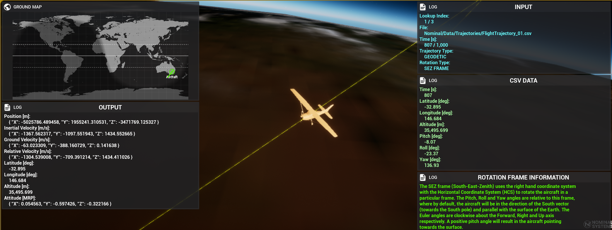
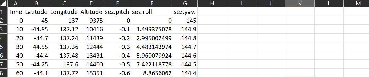
South East Zenith (SEZ) Frame:
SEZ.Pitch: This is the SEZ frame where the right-vector is in the local South direction, the up-vector is in the zenith direction perpendicular to the surface of the planet and the forward-vector is in the local East direction. This field describes the pitch angle clockwise about the forward axis in degrees.SEZ.Roll: This is the SEZ frame where the right-vector is in the local South direction, the up-vector is in the zenith direction perpendicular to the surface of the planet and the forward-vector is in the local East direction. This field describes the roll angle clockwise about the right axis in degrees.SEZ.Yaw: This is the SEZ frame where the right-vector is in the local South direction, the up-vector is in the zenith direction perpendicular to the surface of the planet and the forward-vector is in the local East direction. This field describes the yaw angle clockwise about the up axis in degrees.
Some examples of the data using these formats are shown below. The combination of inertial and geodetic positions with inertial and HCS rotations can be changed between each lookup table but the fields MUST only include one type of position data and one type of rotation data.
Note
The names of the columns are not case-sensitive and upper or lower-case names can be used. However, they must be spelt correctly and no empty columns must be added between the main parameters.
When looking up data in the lookup table, the spacecraft will calculate the velocity and attitude rate using the time derivative of the values listed in the table. It uses a linear approximation to determine these values which is useful for continuing a flight path past the end of the tabulated data.
Setting the Trajectory
In all cases, a custom trajectory can be initialized using the SetCustomTrajectory function that is exposed on the Spacecraft class. This takes in several parameters, with the main parameter being the relative path to the lookup table.
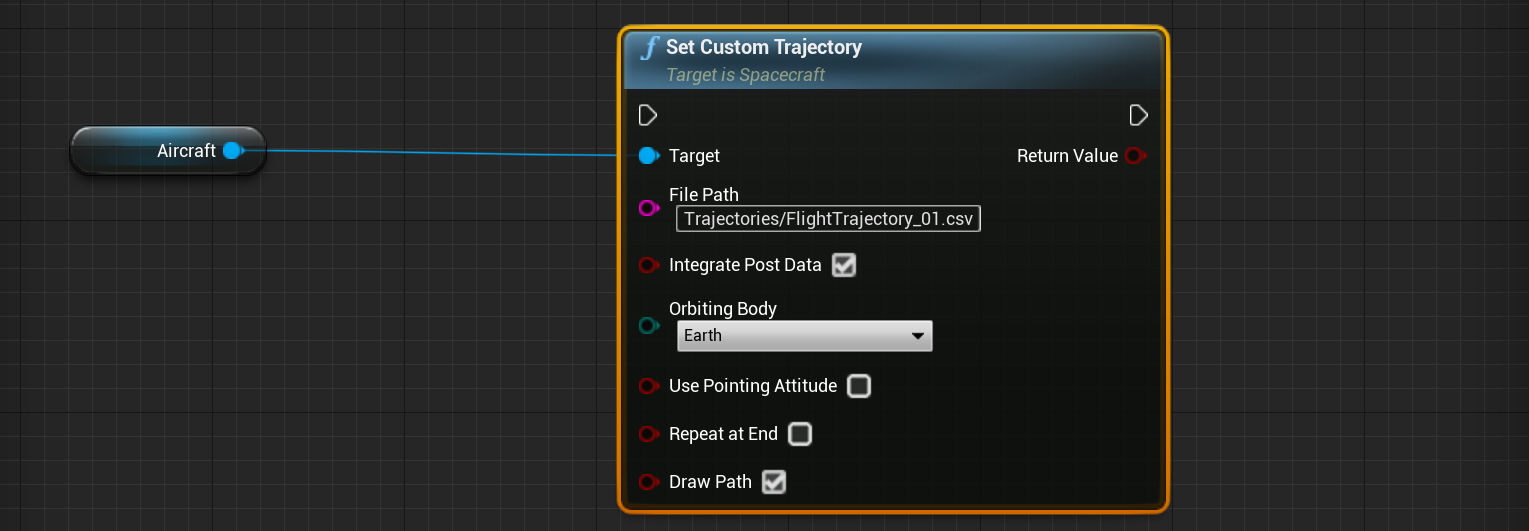
Several parameters can be edited on the trajectory:
- File Path: This can be either the full file path to the lookup table file or just the name of the file. The system will look at all files within the data directory and attempt to match a file with the exact name entered. This makes it easier to set files without having to find the full path to the file.
- Integrate Post Data: If this flag is enabled, once the data has exhausted from the file (when the simulation time is greater than the last time listed on the file), the simulation will continue to move the object at the same velocity as specified by the end of the file. If the flag is disabled, the spacecraft will stop moving once the data has reached the end.
- Orbiting Body: This specifies which planet the object will be orbiting around. In the case of the geodetic table data, this will specify which location planet the spacecraft should be orbiting.
- Use Pointing Attitude: If a rotation is not entered in the lookup table, this flag will orient the object to be in the direction of the velocity. This is useful for flight paths as it will automatically adjust the attitude of the object in the direction that it is moving.
- Repeat At End: This flag will repeat the data from the beginning of the set when the end of the lookup table is reached. This is useful for creating looping orbits in a simulation.
- Draw Path: If this flag is enabled, the flight path will be drawn to the screen in Unreal showing the path of the object and where it is moving towards.
The return value from the function will return whether the file could be found and if the spacecraft was initialized correctly. It is important to note that when using the custom trajectories, no component on board the spacecraft can adjust the positions of the spacecraft or affect such position during the trajectory part of the orbit. Functionality can be resumed once the trajectory is exhausted from the data table and the integrate post-data flag is turned on.