Editor: Deployment and Analysis of Solar Panels
Description
This operator guide gives an example usage for a deployable solar panel on a spacecraft. It shows how to set up the spacecraft with a deployable solar panel, and how to obtain relevant data from the panel such as the solar pointing angle and solar panel power.
In this guide, a spacecraft is created with a deployable solar panel, which is initially stowed. The spacecraft is then pointed at the sun using a sun-pointing software chain, after which the solar panel is deployed, exposing the solar panel to the sun and providing power to the spacecraft.
Learning Outcomes
- Constructing a deployable solar panel using a hinged rigid body
- Actuating a deployable solar panel
- Using a deployable solar panel with a guidance computer to point at the Sun
- Obtaining data from the solar panel
Instructions
Creating the Spacecraft
Start by configuring a level with a spacecraft spawned in orbit. For this guide, an empty 3U spacecraft is used.

Adding the Attitude Control
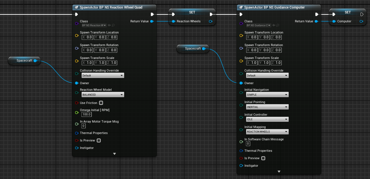
For this guide, the spacecraft will be pointed at the Sun. This requires a means of controlling the spacecraft’s attitude, here using Reaction Wheels, and an appropriate-configured Guidance Computer. First add the Reaction Wheels and the Guidance Computer. Here these are done in the Event Graph, but could also have been implemented in the spacecraft blueprint.
Then add the navigator to get information about the Sun’s location, and configure the Guidance Computer to point the spacecraft at the Sun.
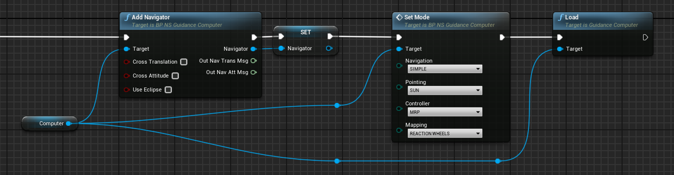
By calling the Load method on the computer before any solar panel is added, the guidance computer will operate as if there is no solar panel on the spacecraft, and simply point the spacecraft body in the direction of the Sun.
Adding the Hinged Rigid Body
The deployment of the solar panel will be achieved by a Hinged Rigid Body. This component is a panel-like rigid structure that can be attached to a spacecraft at a hinge point. The hinge is modelled using first-order dynamics, including a torsional spring constant K (Nm/rad) and rotational damping constant C (Nms/rad). The position of the hinge on the spacecraft is given by the Spawn Transform Location. In this case, it is positioned on the bottom (negative Z) edge of the spacecraft. The constant D (m) defines the centre-of-mass for the hinged portion of the hinged rigid body, including all components attached to the hinged rigid body. It is the distance of the centre-of-mass from the hinge axis. It is set to 0.15 m here, which is half the length of the spacecraft.
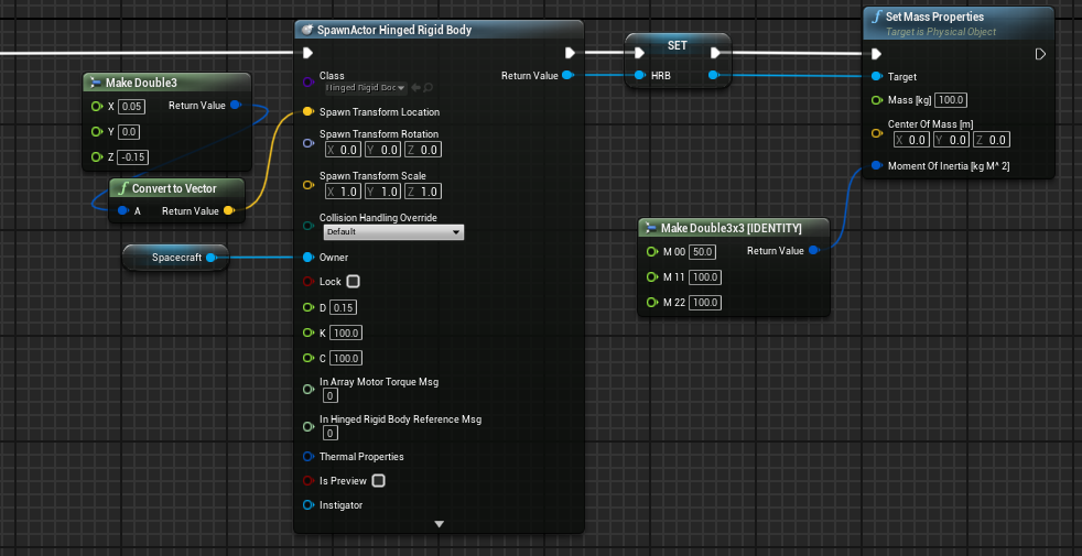
After it is spawned, the Mass and Moment of Inertia of the hinged rigid body are defined. The hinged rigid body is modelled with a diagonal moment of inertia, which suits a flat panel such as a solar panel. Defining the moment of inertia here ensures it remains diagonal, even if other components are added to the hinged rigid body later.
Details on the modelling for the hinged rigid body can be found in TM - Actuator: Hinged Rigid Body.
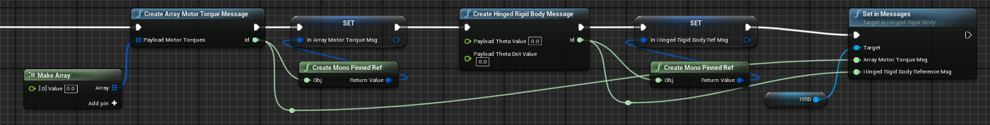
Next, the input messages for the hinged rigid body are defined. A Motor Torque can be specified, as well as a Reference Angle, which defines the natural resting position of the torsional spring. Both of these values are initialised to 0.
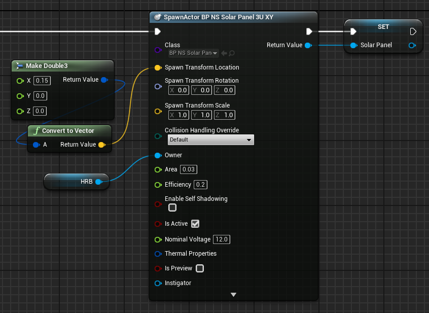
Adding the Solar Panel to the Hinged Rigid Body
The solar panel is added to the spacecraft with the Owner set to the hinged rigid body.
The Spawn Transform Location is set with the X offset equal to 0.15 m, which positions the edge of the solar panel at the hinge. The solar panel is 0.3 m long, so the centre-of-mass is 0.15 m away from the hinge, which matches the value set for the D constant for the hinged rigid body.
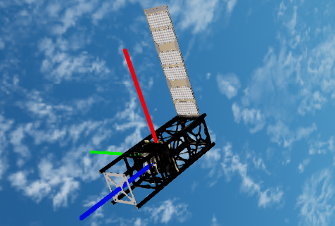
Finally, a rotation is used to orient the hinged rigid body relative to the spacecraft. By default, the hinge axis is aligned with the spacecraft Y axis, and the panel normal is facing in the positive Z direction of the spacecraft. In this case, the panel should lie flat on the side of the spacecraft, along the spacecraft Z axis, so a rotation is added to rotate the panel -90 degrees about the local Y axis.
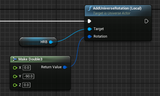
When deployed, the solar panel will rotate back 90 degrees about the Y axis to face the positive Z direction, which, due to the spacecraft’s attitude control, will be pointing in the direction of the Sun.
Actuating the Hinged Rigid Body
There are multiple ways to actuate a hinged rigid body. One method is to set the reference angle for the spring constant to the desired angle, then let the spring force actuate the panel.
In this guide, a motor-driven deployment is considered. The motor is activated after 700 seconds of simulation time, after which a constant torque of 1.0 Nm is applied, and is maintained until the hinged panel reaches an angle of 90 degrees. During the actuation, the spring component of the hinge is disabled by setting the reference angle equal to the current panel angle. At the end of the actuation, the reference angle is set to 90 degrees. This models latching of the hinged panel in the stowed and deployed positions.
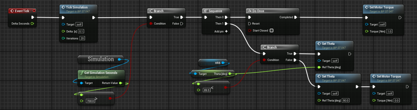
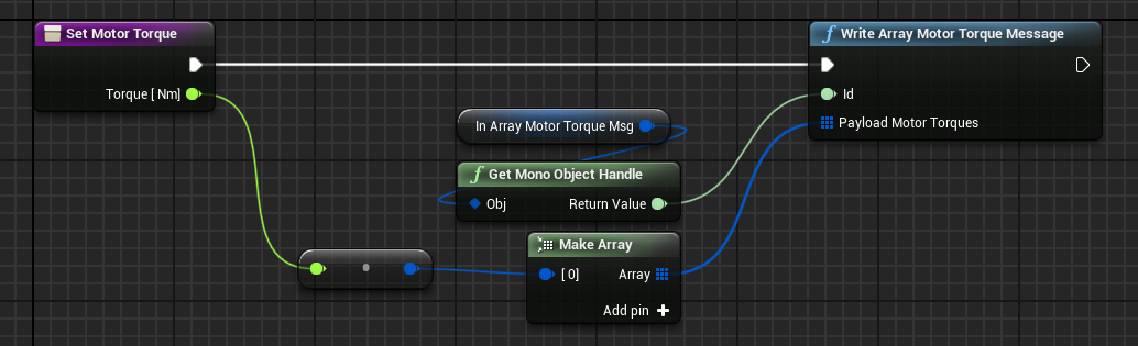
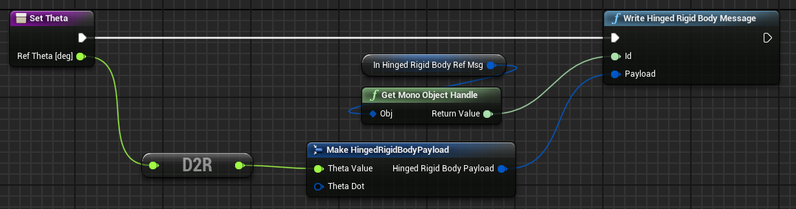
Blueprint functions are used to set the Motor Torque and the reference angle Theta
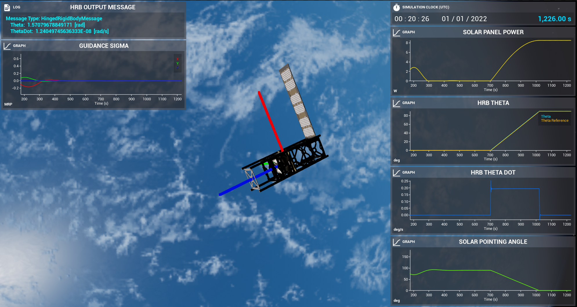
Analysis of Solar Panels
The solar panel can be analyzed through the value of the Power variable, which increases with the cosine of the angle to the Sun.
Data on the hinged rigid body can also be inspected, in particular the angle of the panel Theta, the reference angle, and the ThetaDot, which is the time rate of change of Theta.
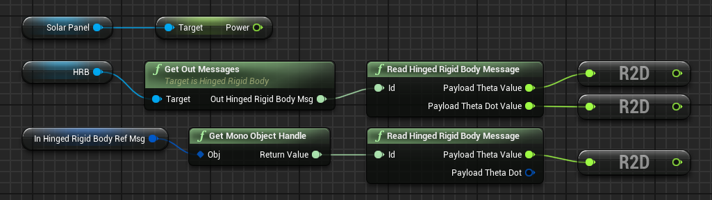
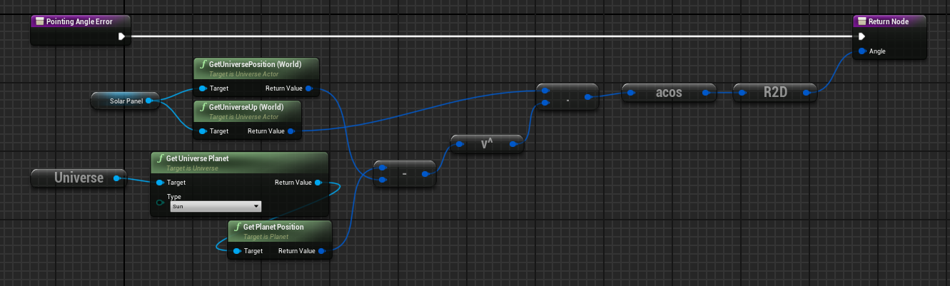
The angle between the panel and the Sun can also be calculated directly. This is done by taking the dot product of the solar panel’s normal vector and the unit vector pointing from the solar panel centre to the Sun.
Typical data for the scenario described in this guide is shown below.